Difference between revisions of "ROM-2820 user guide"
| (86 intermediate revisions by the same user not shown) | |||
| Line 1: | Line 1: | ||
| − | + | = '''產品介紹''' = | |
| − | |||
| − | = 產品介紹 = | ||
== '''產品特性(Features)''' == | == '''產品特性(Features)''' == | ||
| Line 25: | Line 23: | ||
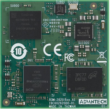
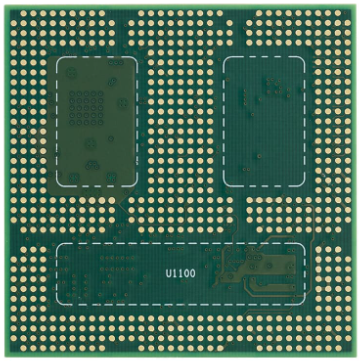
=== '''ROM-2820 接口布局圖 Board Dimension Layout ''' === | === '''ROM-2820 接口布局圖 Board Dimension Layout ''' === | ||
| − | [[File:ROM-2820 Module A.PNG]] [[File:ROM-2820 Module B.PNG]] | + | [[File:ROM-2820 Module A.PNG|RTENOTITLE]] [[File:ROM-2820 Module B.PNG|RTENOTITLE]] |
| | ||
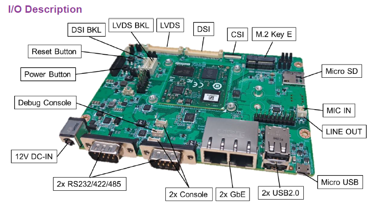
| − | === '''ROM- | + | === '''ROM-ED93 接口布局圖 Board Dimension Layout''' === |
| − | | + | [[File:ROM-2820 io interduce.PNG|RTENOTITLE]] |
| − | |||
| − | |||
=== '''主板内置插针式引脚排序方式 (Pin Header defination) ''' === | === '''主板内置插针式引脚排序方式 (Pin Header defination) ''' === | ||
| Line 39: | Line 35: | ||
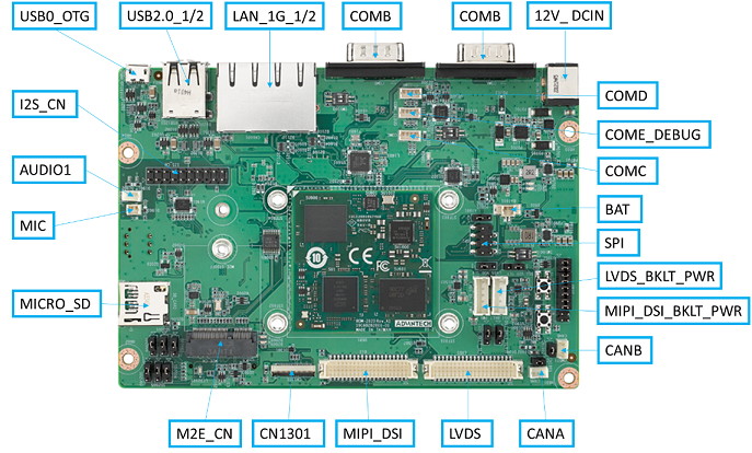
=== '''Internal I/O, Jummper/Switch List:''' === | === '''Internal I/O, Jummper/Switch List:''' === | ||
| − | {| border="1" cellpadding="1" cellspacing="1" style="width: | + | {| border="1" cellpadding="1" cellspacing="1" style="width: 500px;" |
| + | |- | ||
| + | | '''Position''' | ||
| + | | '''Description''' | ||
| + | |- | ||
| + | | [[AT801|AT801]] | ||
| + | | AT/ATX select header | ||
| + | |- | ||
| + | | [[AUDIO1|AUDIO1]] | ||
| + | | Line Out Connector | ||
| + | |- | ||
| + | | [[BAT601|BAT601]] | ||
| + | | Battery Connector | ||
| + | |- | ||
| + | | [[CN1301|CN1301]] | ||
| + | | Camera FPC connector | ||
| + | |- | ||
| + | | [[CN1801|CN1801]] | ||
| + | | CANA terminal resistor enable jumper | ||
| + | |- | ||
| + | | [[CN1802|CN1802]] | ||
| + | | CANB terminal resistor enable jumper | ||
| + | |- | ||
| + | | [[CANA|CANA]] | ||
| + | | CAN Bus Connector | ||
| + | |- | ||
| + | | [[CANB|CANB]] | ||
| + | | CAN Bus Connector | ||
| + | |- | ||
| + | | [[COMA|COMA]] | ||
| + | | RS232/422/485 | ||
| + | |- | ||
| + | | [[COMB|COMB]] | ||
| + | | RS232/422/485 | ||
| + | |- | ||
| + | | [[COMC|COMC]] | ||
| + | | COM A port wafer | ||
| + | |- | ||
| + | | [[COMD|COMD]] | ||
| + | | COM D port wafer | ||
| + | |- | ||
| + | | [[COME_DEBUG|COME_DEBUG]] | ||
| + | | Debug console wafer | ||
| + | |- | ||
| + | | [[CN1601|CN1601]] | ||
| + | | RJ45 1x2 | ||
| + | |- | ||
| + | | [[DCIN701|DCIN701]] | ||
| + | | 12V DCIN connector | ||
| + | |- | ||
| + | | [[DSI|DSI]] | ||
| + | | DSI connector | ||
| + | |- | ||
| + | | [[DSI_BKLT_PWR|DSI_BKLT_PWR]] | ||
| + | | DSI blacklight wafer | ||
| + | |- | ||
| + | | [[DSI_BKLT_SLT|DSI_BKLT_SLT]] | ||
| + | | DSI blacklight power select | ||
| + | |- | ||
| + | | [[DSI_VDD_SLT|DSI_VDD_SLT]] | ||
| + | | DSI VDD power select | ||
| + | |- | ||
| + | | [[GPIO|GPIO]] | ||
| + | | GPIO header | ||
|- | |- | ||
| − | | | + | | [[I2S_CN|I2S_CN]] |
| − | + | | Audio expander pin header | |
| − | | | ||
| − | | | ||
|- | |- | ||
| − | | | + | | [[LVDS|LVDS]] |
| − | | | + | | LVDS connector |
| − | |||
| − | |||
|- | |- | ||
| − | | | + | | [[LVDS_BKLT_PWR|LVDS_BKLT_PWR]] |
| − | + | | LVDS blacklight wafer | |
| − | | | ||
| − | | | ||
|- | |- | ||
| − | | | + | | [[LVDS_BKLT_SLT|LVDS_BKLT_SLT]] |
| − | + | | LVDS blacklight power select | |
| − | | | ||
| − | | | ||
|- | |- | ||
| − | | | + | | [[LVDS_VDD_SLT|LVDS_VDD_SLT]] |
| − | + | | LVDS VDD power select | |
| − | | | ||
| − | | | ||
|- | |- | ||
| − | | | + | | [[M2B_CN|M2B_CN]] |
| − | + | | M2 Key B connector | |
| − | | | ||
| − | | | ||
|- | |- | ||
| − | | | + | | [[M2E_CN|M2E_CN]] |
| − | + | | M2 Key E connector | |
| − | | | ||
| − | | | ||
|- | |- | ||
| − | | | + | | [[MIC|MIC]] |
| − | | | + | | MIC Connector |
| − | |||
| − | |||
|- | |- | ||
| − | | | + | | [[SD_CARD|SD_CARD]] |
| − | + | | Micro SD slot | |
| − | | | ||
| − | | | ||
|- | |- | ||
| − | | | + | | [[SD2001|SD2001]] |
| − | + | | SDIO device select jumper | |
| − | | | ||
| − | | | ||
|- | |- | ||
| − | | | + | | [[SD2002|SD2002]] |
| − | + | | SDIO device select jumper | |
| − | | | ||
| − | | | ||
|- | |- | ||
| − | | | + | | [[SD2003|SD2003]] |
| − | + | | SDIO device select jumper | |
| − | | | ||
| − | | | ||
|- | |- | ||
| − | | | + | | [[SD2005|SD2005]] |
| − | + | | SDIO device select jumper | |
| − | | | ||
| − | | | ||
|- | |- | ||
| − | | | + | | [[SD2004|SD2004]] |
| − | + | | SDIO device select jumper | |
| − | | | ||
| − | | | ||
|- | |- | ||
| − | | | + | | [[SD2006|SD2006]] |
| − | + | | SDIO device select jumper | |
| − | | | ||
| − | | | ||
|- | |- | ||
| − | | | + | | [[SIM|SIM]] |
| − | + | | SIM card connector | |
| − | | | ||
| − | | | ||
|- | |- | ||
| − | | | + | | [[SPI|SPI]] |
| − | | | + | | SPI pin header |
| − | |||
| − | |||
|- | |- | ||
| − | | | + | | [[SW1001|SW1001]] |
| − | + | | Boot select switch | |
| − | | | ||
| − | |||
|- | |- | ||
| − | | | + | | [[SW1002|SW1002]] |
| − | + | | Reset button | |
| − | | | ||
| − | | | ||
|- | |- | ||
| − | | | + | | [[SW1003|SW1003]] |
| − | | | + | | Power button |
| − | |||
| − | |||
| − | |||
| − | |||
| − | |||
| − | |||
| − | |||
| − | |||
| − | |||
| − | |||
| − | |||
|- | |- | ||
| − | | | + | | [[SW1104|SW1104]] |
| − | | | + | | COMA UART setting switch |
|- | |- | ||
| − | | | + | | [[SW1103|SW1103]] |
| − | | | + | | COMB UART setting switch |
|- | |- | ||
| − | | | + | | [[USB1201|USB1201]] |
| − | | | + | | USB2.0 2x1 Connector |
|- | |- | ||
| − | | | + | | [[USB0_OTG1|USB0_OTG1]] |
| − | | | + | | Micro USB Connector |
|} | |} | ||
| − | + | [[File:ROM-2820 io interduce 2-1.png|RTENOTITLE]] | |
| − | |||
| − | |||
| − | |||
| − | |||
| − | |||
| − | |||
| − | |||
| − | |||
| − | |||
| − | |||
| − | |||
| − | |||
| − | |||
| − | |||
| − | |||
| − | |||
| − | + | [[File:ROM-2820 io interduce3-1.png|RTENOTITLE]] | |
| − | + | [[File:ROM-2820 io interduce4.png|RTENOTITLE]] | |
| − | + | = '''快速入門 (Quick Start)''' = | |
| − | |||
| − | |||
| − | |||
| − | |||
| − | |||
| − | |||
| − | |||
| − | |||
| − | |||
| − | |||
| − | |||
| − | |||
| − | |||
| − | |||
| − | |||
| − | |||
| − | |||
| − | |||
| − | |||
| − | |||
| − | |||
| − | |||
| − | |||
| − | |||
| − | |||
| − | |||
| − | |||
| − | |||
| − | |||
| − | |||
| − | |||
| − | |||
| − | |||
=== '''系统下载 (OS Download)''' === | === '''系统下载 (OS Download)''' === | ||
| Line 224: | Line 185: | ||
*'''Linux系统 (Linux OS)'''''' ''' | *'''Linux系统 (Linux OS)'''''' ''' | ||
| − | '''Yocto 4.2: '''IoTGateway/BSP/Linux/iMX8/OS Support List 4.2 release ROM-2820 - ESS-WIKI (advantech.com.tw)''' ''' | + | '''Yocto 4.2: '''[https://ess-wiki.advantech.com.tw/view/Release_Note_ROM-2820 IoTGateway/BSP/Linux/iMX8/OS Support List 4.2 release ROM-2820 - ESS-WIKI (advantech.com.tw)''' '''] |
| − | |||
| − | |||
| | ||
| Line 236: | Line 195: | ||
Step0: 檢查SD卡在Linux 環境的代號 (check SD card symbol in Linux system) | Step0: 檢查SD卡在Linux 環境的代號 (check SD card symbol in Linux system) | ||
| − | [[File:ROM- | + | [[File:ROM-2820 sd check.PNG|RTENOTITLE]] |
Step1: 創造一張可開機的SD 卡 (Create a bootable SD card) | Step1: 創造一張可開機的SD 卡 (Create a bootable SD card) | ||
| Line 242: | Line 201: | ||
<span style="font-size:small;">Command :</span> | <span style="font-size:small;">Command :</span> | ||
| − | + | sudo dd if=2820A1AIM36LIVD0042_iMX93_2G_2024-05-26.img of=/dev/sdh bs=1M conv=fsync<br/> [[File:ROM-2820 sd created.PNG|RTENOTITLE]] | |
| − | |||
| − | |||
Step2: 將可開機的SD 卡插入底板SD卡卡槽(Plug the SD card into Carrier board 's SD card slot) | Step2: 將可開機的SD 卡插入底板SD卡卡槽(Plug the SD card into Carrier board 's SD card slot) | ||
| Line 250: | Line 207: | ||
Step3: 確認開機選擇指撥開關 | Step3: 確認開機選擇指撥開關 | ||
| − | | + | {| border="1" cellpadding="1" cellspacing="1" style="width: 500px;" |
| + | |- | ||
| + | | '''SD boot:''' | ||
| + | | '''1 on , 2on''' | ||
| + | |- | ||
| + | | '''EMMC boot:''' | ||
| + | | '''1 off , 2 on ''' | ||
| + | |} | ||
| + | |||
| + | '''AT/ATX mode Jumper ''' | ||
{| border="1" cellpadding="1" cellspacing="1" style="width: 500px;" | {| border="1" cellpadding="1" cellspacing="1" style="width: 500px;" | ||
|- | |- | ||
| − | | | + | | style="width: 255px;" | '''AT mode''' |
| − | + | | style="width: 232px;" | '''2&3''' | |
| − | | | ||
| − | | | ||
| − | | | ||
|- | |- | ||
| − | | | + | | style="width: 255px;" | '''ATX mode''' |
| − | | | + | | style="width: 232px;" | '''1&2''' |
|} | |} | ||
| + | |||
| + | [[File:ROM-2820 AT ATX mode.png|RTENOTITLE]] | ||
| + | |||
| + | === <span style="font-size:medium;">'''System ID : root'''</span> === | ||
| + | |||
| + | === <span style="font-size:medium;">'''Password : 12345678'''</span> === | ||
Step4:打開電源 和 終端機 (Turn on the Power & Terminal) | Step4:打開電源 和 終端機 (Turn on the Power & Terminal) | ||
| − | | + | [[File:TeraTerm 2021-09-10 140930n.jpg|RTENOTITLE]] |
| + | |||
| + | [[File:TeraTerm12021-09-10 141114n.jpg|RTENOTITLE]] | ||
| + | |||
| + | Step 5: 按下Power 開關 (Turn on Power , open terminal , then press the Power Button ) | ||
| + | |||
| + | SW1003 : PWR_Button , SW1002: Reset_Button | ||
| + | |||
| + | [[File:ROM-2820 Power Button.jpg|RTENOTITLE]] | ||
| + | |||
| + | [[File:ROM-2820 SD bootup.png|RTENOTITLE]] | ||
| − | + | Step6: 複製flash tool到U盤中, 解壓縮flash tools檔案,(copy to USB Disk, then unzip the flash tools file)(Test with 32G SD card) | |
複製檔案到U盤中 (Copy the flash file to USB Disk), 解壓縮flash tool到home目錄(Unzip the file to home) | 複製檔案到U盤中 (Copy the flash file to USB Disk), 解壓縮flash tool到home目錄(Unzip the file to home) | ||
| − | # | + | # Format your USB Disk to ext2 format |
| − | | + | Command : sudo mkfs.ext2 -F /dev/sdX |
| + | |||
| + | 2. Unzip the flash file in your linux system | ||
| + | |||
| + | [[File:ROM-2820 unzip flashfile.PNG|RTENOTITLE]] | ||
| + | |||
| + | 3. Copy the flash file into USB DISK | ||
| + | |||
| + | [[File:ROM-2820 USB DISK FILE.PNG|RTENOTITLE]] | ||
| − | + | 4. 進入flsah tool下的mk_inand資歷夾, 執行指令./mksd-linux.sh /dev/mmcblk0燒錄image到eMMC(Connect USB Disk to ROM-2820 system, extract the flash tool and browser to mk_inand folder and execute flash shell script "./mksd-linux.sh /dev/mmcblk0" | |
解壓縮後如果沒有mksd-linux.sh檔案, 可以到以下連結下載並複製到mk_inand資料夾下(If there is no mksd-linux.sh file in mk_inand directory. Please download from the link below and place it in mk_inand directory: | 解壓縮後如果沒有mksd-linux.sh檔案, 可以到以下連結下載並複製到mk_inand資料夾下(If there is no mksd-linux.sh file in mk_inand directory. Please download from the link below and place it in mk_inand directory: | ||
| − | [https://github.com/ADVANTECH-Corp/RISC_tools_scripts/blob/kirkstone/imx8/mksd-linux.sh mksd-linux.sh] | + | === '''下載 [https://github.com/ADVANTECH-Corp/RISC_tools_scripts/blob/kirkstone/imx8/mksd-linux.sh mksd-linux.sh]''' === |
{| border="1" cellpadding="1" cellspacing="1" style="width: 500px;" | {| border="1" cellpadding="1" cellspacing="1" style="width: 500px;" | ||
|- | |- | ||
| − | | ROM-2820 | + | | '''ROM-2820''' |
| − | | Device node | + | | '''Device node''' |
|- | |- | ||
| − | | SD card | + | | '''SD card''' |
| − | | /dev/ | + | | '''/dev/mmcblk1''' |
|- | |- | ||
| − | | eMMC | + | | '''eMMC''' |
| − | | /dev/mmcblk0 | + | | '''/dev/mmcblk0''' |
|} | |} | ||
| − | + | [[File:ROM-2820 USB DISK FlashEMMC.PNG|RTENOTITLE]] | |
| − | + | Step 7 . 移除SD card , 切換開機switch來設定成從eMMC開機(Romve SD card and Change boot switch to boot from eMMC. Reboot system). | |
| − | | + | {| border="1" cellpadding="1" cellspacing="1" style="width: 500px;" |
| + | |- | ||
| + | | SD boot: | ||
| + | | 1 on , 2on | ||
| + | |- | ||
| + | | EMMC boot: | ||
| + | | 1 off , 2 on | ||
| + | |} | ||
| + | |||
| + | [[File:ROM-2820 Boot From eMMC.PNG|RTENOTITLE]] | ||
=== '''Debug 串口調試 (Debug port Setting)''' === | === '''Debug 串口調試 (Debug port Setting)''' === | ||
| − | 以 Tera Term 为例介绍如何使用串口调试功能 | + | 以 Tera Term 为例介绍如何使用串口调试功能 |
Tera Term Tool | Tera Term Tool | ||
| Line 320: | Line 316: | ||
Log into Terminal Tool (进入串口调试终端): | Log into Terminal Tool (进入串口调试终端): | ||
| − | [[File:ROM- | + | [[File:ROM-2820 DebugMessage.JPG|RTENOTITLE]] |
| − | | + | = '''Linux系统的基本使用(Linux System Basic Operating Method)''' = |
| − | = ''' | + | === '''Recovery by UUU Tool 使用方法(Mirco USB Connection (OTG port))''' === |
| − | + | '''Connect Mirco USB cable to USB OTG port.''' | |
| − | + | [[File:ROM-2820 Mirco USB s.JPG|RTENOTITLE]] | |
| − | '''Change boot switch to " " to boot from force recovery mode.''' | + | '''Change boot switch to "SW1001 " to boot from force recovery mode.''' |
| − | + | [[File:ROM-2820 recovery mode SW1001.jpg|RTENOTITLE]] | |
| − | {| border="1" cellpadding="1" cellspacing="1" style="width: | + | {| border="1" cellpadding="1" cellspacing="1" style="width: 287px;" |
|- | |- | ||
| − | | Serial download: | + | | style="width: 114px;" | Serial download: |
| − | | | + | | style="width: 160px;" | 1on , 2 off |
|} | |} | ||
| Line 355: | Line 351: | ||
1. Download uuu | 1. Download uuu | ||
| − | <div style="background:#eeeeee;border:1px solid #cccccc;padding:5px 10px;">$ wget [https://github.com/nxp-imx/mfgtools/releases/download/uuu_1.4.193/uuu https://github.com/nxp-imx/mfgtools/releases/download/uuu_1.4.193/uuu]<br/> $ chmod a+x uuu<br/> | + | <div style="background:#eeeeee;border:1px solid #cccccc;padding:5px 10px;">$ wget [https://github.com/nxp-imx/mfgtools/releases/download/uuu_1.4.193/uuu https://github.com/nxp-imx/mfgtools/releases/download/uuu_1.4.193/uuu]<br/> $ chmod a+x uuu<br/> </div> |
| + | <span style="tab-stops:152.0pt 152.05pt">Connect OTG to Ubuntu System(x86 PC) , make sure the device was identified</span> | ||
| + | |||
| + | [[File:ROM-2820 LsUSB Mirco usb.JPG|RTENOTITLE]] | ||
| + | |||
Type command below to flash eMMC: | Type command below to flash eMMC: | ||
| − | <div style="background:#eeeeee;border:1px solid #cccccc;padding:5px 10px;"> | + | <div style="background:#eeeeee;border:1px solid #cccccc;padding:5px 10px;"> |
| − | [[File:ROM- | + | <span lang="EN-US" style="font-size:10.0pt"># </span><span lang="EN-US" style="font-size:10.0pt">tar -xvzf 2820A1AIM36LIVD0042_iMX93_2G_flash_tool.tgz</span> |
| + | |||
| + | <span lang="EN-US" style="font-size:10.0pt"># cd 2820A1AIM36LIVD0042_iMX93_2G_flash_tool/image/</span> | ||
| + | |||
| + | <span style="line-height:102%"><span lang="EN-US" style="font-size:10.0pt"><span style="line-height:102%"># sudo ./uuu -b emmc_all imx-image-full-imx93rom2820a1-20240321094239.rootfs.wic</span></span></span> | ||
| + | </div> | ||
| + | [[File:ROM-2820 UUU flash Done.png|RTENOTITLE]] | ||
| + | |||
| + | === '''Display Setting (ROM-2820)''' === | ||
| + | |||
| + | === '''LVDS''' === | ||
| + | |||
| + | Single Channel LVDS: G070VW01 (VDD: 3.3V, Backlight Power: 12V) | ||
| + | |||
| + | Step 1: Connect G070VW01 LVDS panel with the LVDS cable. Connect this to the LVDS. Connect the Backlight cable to LVDS_BKLT_PWR.<br/> Step 2: Connect another 12V adapter to the DC-Jack on the backlight cable. <br/> Step 3: Power on RSB-2820 and the extra 12V adapter.<br/> Step 4: Press enter after boot. The system will stop at u-boot as demonstrated below, enter the command in red and press enter. | ||
| − | | + | [[File:ROM-2820 LVDS setting.jpg|RTENOTITLE]] |
| + | |||
| + | '''<span style="line-height:120%">(LVDS_BPLT_SLT : 2&3 jumper short)</span>''' | ||
| + | <div style="background:#eeeeee;border:1px solid #cccccc;padding:5px 10px;">Normal Boot<br/> Hit any key to stop autoboot: 0<br/> => setenv fdtfile imx93-rom2820-a1-lvds.dtb<br/> => saveenv<br/> => boot</div> | ||
| + | === '''MIPI HDMI''' === | ||
| + | |||
| + | Single Channel MIPI HDMI: (VDD: 3.3V, Backlight Power: 5V) | ||
| + | |||
| + | Step 1: Connect another 5V adapter to the DC-Jack on the backlight cable. <br/> Step 2: Power on RSB-2820 and the extra 5V adapter.<br/> Step 3: Press enter after boot. The system will stop at u-boot as demonstrated below, enter the command in red and press enter. | ||
| + | |||
| + | [[File:ROM-2820 MIPI HDMI setting1.JPG|RTENOTITLE]] | ||
| + | |||
| + | '''<span style="line-height:120%">(LVDS_BPLT_SLT : 2&3 jumper short)</span>''' | ||
| + | <div style="background:#eeeeee;border:1px solid #cccccc;padding:5px 10px;"> Normal Boot<br/> Hit any key to stop autoboot: 0<br/> => setenv fdtfile imx93-rom2820-a1.dtb<br/> => saveenv<br/> => boot</div> | ||
| + | === '''MIPI DSI''' === | ||
| − | | + | Single Channel LVDS: G101UAN02.0 (VDD: 3.3V, Backlight Power: 12V)<br/> Step 1: Connect G101UAN02.0 LVDS panel with the LVDS cable. Connect this to theLVDS. Connect the Backlight cable to DSI_BKLT_PWR.<br/> Step 2: Connect another 12V adapter to the DC-Jack on the backlight cable. <br/> Step 3: Power on RSB-2820 and the extra 12V adapter.<br/> Step 4: Press enter after boot. The system will stop at u-boot as demonstrated below, enter the command in red and press enter. |
| − | + | [[File:ROM-2820 MIPI DSI setting.jpg|RTENOTITLE]] | |
| − | === ''' | + | '''(DSI_BKLT_SLT: 2&3 jumper short)''' |
| + | <div style="background:#eeeeee;border:1px solid #cccccc;padding:5px 10px;">Normal Boot<br/> Hit any key to stop autoboot: 0<br/> => setenv fdtfile imx93-rom2820-a1-auog101uan02.dtb<br/> => saveenv<br/> => boot</div> | ||
| + | === '''Audio(Audio Testing Methid)''' === | ||
| − | + | Step 1: Check audio codec | |
| + | <div style="background:#eeeeee;border:1px solid #cccccc;padding:5px 10px;"> | ||
| + | <span lang="EN-US" style="font-size:10.0pt"># cat /proc/asound/cards</span> | ||
| − | + | <span style="line-height:103%"><span style="tab-stops:73.3pt"><span lang="EN-US" style="font-size:10.0pt"><span style="line-height:103%">0 [sgtl5000 ]: sgtl5000 - <span style="letter-spacing:-.15pt">sgtl5000 </span>sgtl5000</span></span></span></span> | |
| − | < | ||
| − | |||
| + | | ||
| + | </div> | ||
| | ||
| − | + | Step 2: Audio codec (sgtl5000): | |
| + | |||
| + | #<span style="tab-stops:123.65pt">Set MIC and headphone:</span> | ||
| + | <div style="background:#eeeeee;border:1px solid #cccccc;padding:5px 10px;"> | ||
| + | <span style="line-height:103%"><span lang="EN-US" style="font-size:10.0pt"><span style="line-height:103%"># amixer set Mic 100%</span></span></span> | ||
| − | === | + | <span style="line-height:103%"><span lang="EN-US" style="font-size:10.0pt"><span style="line-height:103%">#</span></span> <span lang="EN-US" style="font-size:10.0pt"><span style="line-height:103%">amixer set Headphone 100%</span></span></span> |
| − | < | + | </div> |
| − | |||
| − | < | ||
'''Record and playback:''' | '''Record and playback:''' | ||
| − | <div style="background:#eeeeee;border:1px solid #cccccc;padding:5px 10px;">'''# '''</ | + | <div style="background:#eeeeee;border:1px solid #cccccc;padding:5px 10px;">'''# ''' |
| + | <span lang="EN-US" style="font-size:10.0pt">Record</span> | ||
| + | |||
| + | <span lang="EN-US" style="font-size:10.0pt"># arecord -D plughw:0,0 -r 16000 -f S16_LE ./f-16000.wav</span> | ||
| + | |||
| + | <span lang="EN-US" style="font-size:10.0pt">Playback</span> | ||
| + | |||
| + | <span lang="EN-US" style="font-size:10.0pt"># aplay -D plughw:0,0 f-16000.wav</span> | ||
| + | </div> | ||
| | ||
=== '''M.2 WiFi/BT測試方法(M.2 WiFi/BT Testing Method)''' === | === '''M.2 WiFi/BT測試方法(M.2 WiFi/BT Testing Method)''' === | ||
| − | *Test Wi-Fi with | + | *Test Wi-Fi with NXP IW-612 Module (SDIO Interface) |
| − | <div style="background:#eeeeee;border:1px solid #cccccc;padding:5px 10px;">=> setenv fdtfile | + | |
| − | + | <span style="line-height:102%">Step 1: Switch jumper SD2001~SD2006(2&3 jumper short)</span> | |
| − | <div style="background:#eeeeee;border:1px solid #cccccc;padding:5px 10px;"># | + | |
| − | + | <span style="line-height:102%">[[File:ROM-2820 Jumper SD2001-2006.jpg|RTENOTITLE]]</span> | |
| − | < | + | |
| − | + | Step 2: Press enter after boot. The system will stop at u-boot, and change dtb file by below command. | |
| − | <div style="background:#eeeeee;border:1px solid #cccccc;padding:5px 10px;"># | + | <div style="background:#eeeeee;border:1px solid #cccccc;padding:5px 10px;"> |
| − | *Test | + | <span lang="EN-US" style="font-size:10.0pt"># setenv fdtfile imx93-rom2820-a1-m2-sdio.dtb</span> |
| + | |||
| + | <span lang="EN-US" style="font-size:10.0pt"># saveenv</span> | ||
| + | |||
| + | <span lang="EN-US" style="font-size:10.0pt"># boot</span> | ||
| + | </div> | ||
| + | [[File:ROM-2820 uboot.png|RTENOTITLE]] | ||
| + | |||
| + | Step 3: Install driver by below command. | ||
| + | <div style="background:#eeeeee;border:1px solid #cccccc;padding:5px 10px;"><span lang="EN-US" style="font-size:10.0pt"># modprobe moal mod_para=nxp/wifi_mod_para.conf</span></div> | ||
| + | [[File:ROM-2820 mod para.png|RTENOTITLE]] | ||
| + | |||
| + | Step 4: WIFI test command. | ||
| + | <div style="background:#eeeeee;border:1px solid #cccccc;padding:5px 10px;"> | ||
| + | <span lang="EN-US" style="font-size:10.0pt">#</span><span lang="EN-US" style="font-size:10.0pt">ifconfig mlan0 up</span> | ||
| + | |||
| + | <span lang="EN-US" style="font-size:10.0pt">#</span><span lang="EN-US" style="font-size:10.0pt">wpa_passphrase ${SSID} ${PASSWORD} > /tmp/wpa.conf</span> | ||
| + | |||
| + | <span lang="EN-US" style="font-size:10.0pt">#</span><span lang="EN-US" style="font-size:10.0pt">wpa_supplicant -BDwext -imlan0 -c/tmp/wpa.conf</span> | ||
| + | |||
| + | <span lang="EN-US" style="font-size:10.0pt">#</span><span lang="EN-US" style="font-size:10.0pt">udhcpc -b -i mlan0</span> | ||
| + | </div> | ||
| + | [[File:ROM-2820 mlan0.png|RTENOTITLE]] | ||
| + | |||
| + | [[File:ROM-2820 ifconfig.png|RTENOTITLE]] | ||
| + | |||
| + | Test Bluetooth with NXP IW-612 Module (UART Interface): | ||
| + | |||
| + | <span style="line-height:102%">Step 1: Please refer to the 3.3.1 step 1.</span> | ||
| + | |||
| + | <span style="line-height:102%">Step 2: Please refer to the 3.3.1 step 2.</span> | ||
| + | |||
| + | <span style="line-height:102%">Step 3: Please refer to the 3.3.1 step 3.</span> | ||
| + | |||
| + | <span style="line-height:102%">Step 4: Bluetooth test command.</span> | ||
| + | <div style="background:#eeeeee;border:1px solid #cccccc;padding:5px 10px;"> | ||
| + | <span lang="EN-US" style="font-size:10.0pt"># modprobe btnxpuart</span> | ||
| + | |||
| + | <span lang="EN-US" style="font-size:10.0pt"># hciconfig hci0 up</span> | ||
| + | |||
| + | <span lang="EN-US" style="font-size:10.0pt"># bluetoothctl</span> | ||
| + | |||
| + | <span lang="EN-US" style="font-size:10.0pt"># discoverable on</span> | ||
| + | |||
| + | <span lang="EN-US" style="font-size:10.0pt"># pairable on</span> | ||
| + | |||
| + | <span lang="EN-US" style="font-size:10.0pt"># scan on</span> | ||
| + | |||
| + | <span lang="EN-US" style="font-size:10.0pt"> [NEW] FC:18:3C:8D:75:F4 myphone</span> | ||
| + | |||
| + | <span lang="EN-US" style="font-size:10.0pt"># scan off</span> | ||
| + | |||
| + | <span lang="EN-US" style="font-size:10.0pt"># pair FC:18:3C:8D:75:F4</span> | ||
| + | |||
| + | <span lang="EN-US" style="font-size:10.0pt"># connect FC:18:3C:8D:75:F4</span> | ||
| + | </div> | ||
| + | *Test 4G with EWM-C401CQE01 Module (UART Interface) | ||
| + | |||
| + | <span style="line-height:102%">Step1 :You need to connect two antennas.</span> | ||
| + | |||
| + | Step2 : Uboot command | ||
| + | <div style="background:#eeeeee;border:1px solid #cccccc;padding:5px 10px;"> | ||
| + | #setenv fdtfile imx93-rom2820-a1-m2-sdio.dtb | ||
| + | |||
| + | #saveenv | ||
| − | + | #reset | |
| − | + | </div> | |
Step 2: Install driver by below command. | Step 2: Install driver by below command. | ||
| − | <div style="background:#eeeeee;border:1px solid #cccccc;padding:5px 10px;"> | + | <div style="background:#eeeeee;border:1px solid #cccccc;padding:5px 10px;"> #modprobe moal mod_para=nxp/wifi_mod_para.conf</div> |
| − | + | Step3: 4G test command. | |
| − | < | + | <pre style="margin: 1.25pt 0cm 0.0001pt 2pt;"># stty -F /dev/ttyUSB1 speed 115200 -echo |
| − | + | # cat /dev/ttyUSB1 & | |
| + | # echo "AT+CSQ" > /dev/ttyUSB1 | ||
| + | |||
| + | Console message: | ||
| + | AT+CSQ | ||
| − | + | +CSQ: 25,99 | |
| − | + | OK | |
| − | + | # pppd connect 'chat -v -s -t 10 "" "AT" "" "ATDT*99#" "CONNECT" ""' user username password password /dev/ttyUSB2 460800 nodetach crtscts debug usepeerdns defaultroute & | |
| − | + | # ping 8.8.8.8 | |
| + | 64 bytes from 8.8.8.8: icmp_seq=1 ttl=56 time=222 ms</pre> | ||
| | ||
| Line 416: | Line 527: | ||
=== '''Serial Port測試方法(Serial Testing Method)(COM A/C)''' === | === '''Serial Port測試方法(Serial Testing Method)(COM A/C)''' === | ||
| − | + | ==== '''RS-232''' ==== | |
| − | |||
| − | |||
| − | |||
| − | |||
| − | |||
| − | |||
| − | |||
| − | |||
| − | |||
| − | |||
| − | |||
| − | |||
| − | |||
| − | |||
| − | |||
| − | |||
*'''RS-232 Loopback Test (eg. COMA: ttyLP0):''' | *'''RS-232 Loopback Test (eg. COMA: ttyLP0):''' | ||
| − | Step 1: | + | <span style="tab-stops:127.5pt 127.55pt">Step 1:. Connect loopback with COMA(ttyLP4)&COMB(ttyLP5)</span><br/> Step 2: Run test command. |
| − | <div style="background:#eeeeee;border:1px solid #cccccc;padding:5px 10px;"># stty -F /dev/ | + | <div style="background:#eeeeee;border:1px solid #cccccc;padding:5px 10px;"> |
| − | + | <span lang="EN-US" style="font-size:10.0pt"># stty -F /dev/ttyLP4 -echo -onlcr 115200</span> | |
| − | + | <span lang="EN-US" style="font-size:10.0pt"># cat /dev/ttyLP4 &</span> | |
| − | Adam-4520 RX- <-->ROM-2820 COMA DB9 Pin 1,<br/> Adam-4520 RX+ <-->ROM-2820 COMA DB9 Pin 2,<br/> Adam-4520 TX- <-->ROM-2820 | + | <span lang="EN-US" style="font-size:10.0pt"># echo "Serial Port Test" > /dev/ttyLP4</span> |
| + | </div> | ||
| + | | ||
| + | |||
| + | === '''RS-485''' === | ||
| + | |||
| + | '''RS-485 Test:''' | ||
| + | |||
| + | <span style="line-height:102%">Step 1: Test RS-485 with Adam-4520. Connect Adam-4520 with COMA with DB9 as the following(COMA(ttyLP4)&COMB(ttyLP5))</span> | ||
| + | |||
| + | Adam-4520 RX- <-->ROM-2820 COMA DB9 Pin 1,<br/> Adam-4520 RX+ <-->ROM-2820 COMA DB9 Pin 2,<br/> Adam-4520 TX- <-->ROM-2820 COMB DB9 Pin 1,<br/> Adam-4520 TX+ <--> ROM-2820 COMB DB9 Pin 2 | ||
| + | |||
| + | [[File:ROM-2820 RS-485.JPG|RTENOTITLE]] | ||
Step 3: Run below command: | Step 3: Run below command: | ||
<div style="background:#eeeeee;border:1px solid #cccccc;padding:5px 10px;"># stty -F /dev/ttyLP0 speed 115200 ignbrk -brkint -icrnl -imaxbel -opost -onlcr -isig -icanon -iexten -echo -echoe -echok -echoctl -echoke<br/> # cat /dev/ttyLP0 &<br/> # echo "Serial Test" > /dev/ttyLP0</div> | <div style="background:#eeeeee;border:1px solid #cccccc;padding:5px 10px;"># stty -F /dev/ttyLP0 speed 115200 ignbrk -brkint -icrnl -imaxbel -opost -onlcr -isig -icanon -iexten -echo -echoe -echok -echoctl -echoke<br/> # cat /dev/ttyLP0 &<br/> # echo "Serial Test" > /dev/ttyLP0</div> | ||
| − | + | Step 2 :Create the following file and save it as rs485.sh | |
| + | <pre style="margin: 0.5pt 0cm 0.0001pt 2.05pt;">#!/bin/sh | ||
| + | |||
| + | i2cset -y -f 4 0x21 0x00 0x10 | ||
| + | i2cset -y -f 4 0x21 0x01 0x01 | ||
| + | i2cset -y -f 4 0x21 0x02 0xdf | ||
| + | i2cset -y -f 4 0x21 0x03 0xfd | ||
| + | i2cset -y -f 4 0x21 0x04 0x00 | ||
| + | i2cset -y -f 4 0x21 0x05 0x00 | ||
| + | i2cset -y -f 4 0x21 0x06 0xcf | ||
| + | i2cset -y -f 4 0x21 0x07 0xfc | ||
| + | </pre> | ||
| − | Step | + | <span style="line-height:120%">Step 3: Run below command:</span> |
| + | <pre style="margin: 0.5pt 0cm 0.0001pt 2.05pt;"># sudo chmod 775 rs485.sh | ||
| + | # ./rs485.sh | ||
| + | # stty -F /dev/ttyLP4 -echo -onlcr 115200 | ||
| + | # cat /dev/ttyLP4 & | ||
| + | # echo "Serial Port Test" > /dev/ttyLP4 | ||
| + | </pre> | ||
| − | + | Step 4: <span style="line-height:120%">You need to open two terminals: one to connect to the debug port of the ROM2820, and the other to connect to the Adam-4520.</span> | |
| − | Step | + | Step 5:<span style="line-height:120%">You can send data from the ROM2820's debug port to the Adam-4520, and you can also input text from the Adam-4520's terminal using the keyboard so that the ROM2820's debug port can receive it.</span> |
| − | <div style="background:#eeeeee;border:1px solid #cccccc;padding:5px 10px;"> | + | |
| − | + | <span style="line-height:120%">[[File:ROM-2820 485 test.png|RTENOTITLE]]</span> | |
| + | |||
| + | '''I2C測試方法(I2C Testing Method)''' | ||
| + | |||
| + | Step 1: Test command | ||
| + | <div style="background:#eeeeee;border:1px solid #cccccc;padding:5px 10px;"> | ||
| + | <span style="line-height:103%"><span lang="EN-US" style="font-size:10.0pt"><span style="line-height:103%"># i2cdetect -l</span></span></span> | ||
| + | |||
| + | <span style="line-height:103%"><span lang="EN-US" style="font-size:10.0pt"><span style="line-height:103%">i2c-0 i2c 44340000.i2c I2C adapter</span></span></span> | ||
| + | |||
| + | <span style="line-height:103%"><span lang="EN-US" style="font-size:10.0pt"><span style="line-height:103%">i2c-1 i2c 44350000.i2c I2C adapter</span></span></span> | ||
| − | | + | <span style="line-height:103%"><span lang="EN-US" style="font-size:10.0pt"><span style="line-height:103%">i2c-2 i2c 42530000.i2c I2C adapter</span></span></span> |
| − | | + | <span style="line-height:103%"><span lang="EN-US" style="font-size:10.0pt"><span style="line-height:103%">i2c-4 i2c 426b0000.i2c I2C adapter</span></span></span> |
| − | === ''' | + | <span style="line-height:103%"><span lang="EN-US" style="font-size:10.0pt"><span style="line-height:103%">i2c-7 i2c 426e0000.i2c I2C adapter</span></span></span> |
| + | </div> | ||
| + | === '''RS-422 ''' === | ||
| − | + | '''RS-422 Test ''' | |
| − | <div style="background:#eeeeee;border:1px solid #cccccc;padding:5px 10px;"> | + | <div style="background:#eeeeee;border:1px solid #cccccc;padding:5px 10px;">#!/bin/sh</div> <div style="background:#eeeeee;border:1px solid #cccccc;padding:5px 10px;">i2cset -y -f 4 0x21 0x00 0x10</div> <div style="background:#eeeeee;border:1px solid #cccccc;padding:5px 10px;">i2cset -y -f 4 0x21 0x01 0x01</div> <div style="background:#eeeeee;border:1px solid #cccccc;padding:5px 10px;">i2cset -y -f 4 0x21 0x02 0xff</div> <div style="background:#eeeeee;border:1px solid #cccccc;padding:5px 10px;">i2cset -y -f 4 0x21 0x03 0xfd</div> <div style="background:#eeeeee;border:1px solid #cccccc;padding:5px 10px;">i2cset -y -f 4 0x21 0x04 0x00</div> <div style="background:#eeeeee;border:1px solid #cccccc;padding:5px 10px;">i2cset -y -f 4 0x21 0x05 0x00</div> <div style="background:#eeeeee;border:1px solid #cccccc;padding:5px 10px;">i2cset -y -f 4 0x21 0x06 0xcf</div> <div style="background:#eeeeee;border:1px solid #cccccc;padding:5px 10px;">i2cset -y -f 4 0x21 0x07 0xfc</div> |
| | ||
| Line 470: | Line 606: | ||
=== '''USB測試方法(USB Testing Method)''' === | === '''USB測試方法(USB Testing Method)''' === | ||
| − | USB disk test (USB 2.0)<br/> Step 1: Issue the following command (lsusb -t) after inserting a USB disk into the USB 2.0 port to check if the USB device is listed. Step 2: Test (eg. if usb disk is /dev/sda) | + | USB disk test (USB 2.0) |
| − | < | + | |
| − | + | <br/> Step 1:Issue the following command (lsusb -t) after inserting a USB disk into the USB 2.0 port to check if the USB device is listed. | |
| + | |||
| + | Step 2: Test (eg. if usb disk is /dev/sda) | ||
| + | <pre style="margin: 0.1pt 0cm 0.0001pt 2.05pt;"># dd if=/dev/urandom of=data bs=1 count=1024 | ||
| + | # dd if=/dev/sda of=backup bs=1 count=1024 skip=4096 # dd if=data of=/dev/sda bs=1 seek=4096 | ||
| + | # dd if=/dev/sda of=data1 bs=1 count=1024 skip=4096 # diff data data1 | ||
| + | # dd if=backup of=/dev/sda bs=1 seek=4096</pre> | ||
| | ||
| Line 479: | Line 621: | ||
Step 1: Set system time to current, then write to RTC | Step 1: Set system time to current, then write to RTC | ||
| − | <div style="background:#eeeeee;border:1px solid #cccccc;padding:5px 10px;"># date | + | <div style="background:#eeeeee;border:1px solid #cccccc;padding:5px 10px;"><span style="line-height:103%"><span lang="EN-US" style="font-size:10.0pt"><span style="line-height:103%">root@imx93rom2820a1:~# date 010100002025 && hwclock -w && date</span></span></span></div> |
Step 2: Set one incorrect time, then read time from RTC to verify | Step 2: Set one incorrect time, then read time from RTC to verify | ||
| − | <div style="background:#eeeeee;border:1px solid #cccccc;padding:5px 10px;"># | + | <div style="background:#eeeeee;border:1px solid #cccccc;padding:5px 10px;"><span style="line-height:103%"><span lang="EN-US" style="font-size:10.0pt"><span style="line-height:103%">root@imx93rom2820a1:~# hwclock -r && date</span></span></span></div> |
| − | | + | Step 3: Restore the RTC time to system time |
| + | <pre style="margin: 1.35pt 196.45pt 0.0001pt 2.05pt;"> root@imx93rom2820a1:~# date </pre> | ||
=== '''eMMC/SD測使方法(eMMC/SD Testing Method)''' === | === '''eMMC/SD測使方法(eMMC/SD Testing Method)''' === | ||
| Line 491: | Line 634: | ||
'''Step 1: Test command:''' | '''Step 1: Test command:''' | ||
| − | <div style="background:#eeeeee;border:1px solid #cccccc;padding:5px 10px;"> | + | <div style="background:#eeeeee;border:1px solid #cccccc;padding:5px 10px;"># dd if=/dev/urandom of=data bs=1 count=1024<br/> # dd if=/dev/mmcblk0 of=backup bs=1 count=1024 skip=4096<br/> # dd if=data of=/dev/mmcblk0 bs=1 seek=4096<br/> # dd if=/dev/mmcblk0 of=data1 bs=1 count=1024 skip=4096<br/> # diff data data1<br/> # dd if=backup of=/dev/mmcblk0 bs=1 seek=4096</div> |
| | ||
| Line 498: | Line 641: | ||
'''Command : ifconfig ''' | '''Command : ifconfig ''' | ||
| − | + | [[File:ROM-2820 Eth test.JPG|RTENOTITLE]] | |
'''Command: Ping - I eth1 8.8.8.8 or Ping - I eth0 8.8.8.8 ''' | '''Command: Ping - I eth1 8.8.8.8 or Ping - I eth0 8.8.8.8 ''' | ||
| − | + | [[File:ROM-2820 Eth0 test.JPG|RTENOTITLE]] | |
| − | |||
| − | |||
| − | |||
| − | |||
=== '''GPIO使用方法(GPIO Operating Method)''' === | === '''GPIO使用方法(GPIO Operating Method)''' === | ||
| Line 514: | Line 653: | ||
{| border="1" cellpadding="1" cellspacing="1" style="width: 500px;" | {| border="1" cellpadding="1" cellspacing="1" style="width: 500px;" | ||
|- | |- | ||
| − | | | + | | CPU pin to GPIO |
| − | | | + | | GPIO 1101 |
| − | | | + | | Number |
| − | |||
|- | |- | ||
| + | | GPIO1(shared pin) | ||
| 1 | | 1 | ||
| − | | | + | | 496 |
| − | |||
| − | |||
|- | |- | ||
| + | | GPIO2 | ||
| 2 | | 2 | ||
| − | | | + | | 497 |
| − | |||
| − | |||
|- | |- | ||
| + | | GPIO3 | ||
| 3 | | 3 | ||
| − | | | + | | 498 |
| − | |||
| − | |||
|- | |- | ||
| + | | GPIO4 | ||
| 4 | | 4 | ||
| − | | | + | | 499 |
| − | |||
| − | |||
|- | |- | ||
| + | | GPIO5 | ||
| 5 | | 5 | ||
| − | | | + | | 500 |
| − | |||
| − | |||
|- | |- | ||
| + | | GPIO6 | ||
| 6 | | 6 | ||
| − | | | + | | 501 |
| − | |||
| − | |||
|- | |- | ||
| + | | GPIO7 | ||
| 7 | | 7 | ||
| − | | | + | | 502 |
| − | |||
| − | |||
|- | |- | ||
| + | | GPIO8 | ||
| 8 | | 8 | ||
| − | | | + | | 503 |
| − | |||
| − | |||
|- | |- | ||
| + | | GPIO9 | ||
| 9 | | 9 | ||
| − | | | + | | 504 |
| − | |||
| − | |||
|- | |- | ||
| + | | GPIO10 | ||
| 10 | | 10 | ||
| − | | | + | | 505 |
| − | |||
| − | |||
|- | |- | ||
| + | | GPIO11 | ||
| 11 | | 11 | ||
| − | | | + | | 506 |
| − | |||
| − | |||
|- | |- | ||
| + | | GPIO12 | ||
| 12 | | 12 | ||
| − | | | + | | 507 |
| − | |||
| − | |||
| − | |||
| − | |||
| − | |||
| − | |||
| − | |||
| − | |||
| − | |||
| − | |||
| − | |||
| − | |||
| − | |||
| − | |||
| − | |||
| − | |||
| − | |||
| − | |||
| − | |||
| − | |||
| − | |||
| − | |||
| − | |||
| − | |||
| − | |||
| − | |||
| − | |||
| − | |||
| − | |||
| − | |||
| − | |||
| − | |||
| − | |||
| − | |||
| − | |||
| − | |||
| − | |||
| − | |||
| − | |||
| − | |||
| − | |||
| − | |||
|} | |} | ||
| − | GPIO | + | GPIO loop test: |
| + | <pre>Connect GPIO pin#3 and GPIO pin#4 | ||
| − | + | root@imx93rom2820a1:/# echo 498 > /sys/class/gpio/export | |
| − | + | root@imx93rom2820a1:/# echo 499 > /sys/class/gpio/export | |
| − | |||
| − | |||
| − | |||
| − | |||
| − | |||
| − | |||
| − | + | root@imx93rom2820a1:/# echo out > /sys/class/gpio/gpio498/direction | |
| − | + | root@imx93rom2820a1:/# echo in > /sys/class/gpio/gpio499/direction | |
| − | |||
| − | |||
| − | |||
| − | |||
| − | + | root@imx93rom2820a1:/#cat /sys/class/gpio/gpio498/value | |
| − | + | 0 | |
| − | + | root@imx93rom2820a1:/# echo 1 > /sys/class/gpio/gpio498/value | |
| − | |||
| − | |||
| − | |||
| − | |||
| − | |||
| − | |||
| − | |||
| − | |||
| − | |||
| − | |||
| − | + | root@imx93rom2820a1:/# cat /sys/class/gpio/gpio498/value | |
| − | + | 1</pre> | |
| − | + | [[File:ROM-2820 GPIO 3 4.png|RTENOTITLE]] | |
| + | <pre>Connect GPIO pin#5 and GPIO pin #6 | ||
| − | + | root@imx93rom2820a1:/# echo 500 > /sys/class/gpio/export | |
| − | + | root@imx93rom2820a1:/# echo 501 > /sys/class/gpio/export | |
| − | + | root@imx93rom2820a1:/# echo out > /sys/class/gpio/gpio500/direction | |
| − | + | root@imx93rom2820a1:/# echo in > /sys/class/gpio/gpio501/direction | |
| − | + | root@imx93rom2820a1:/# cat /sys/class/gpio/gpio500/value | |
| − | + | 0 | |
| − | + | root@imx93rom2820a1:/# echo 1 > /sys/class/gpio/gpio500/value | |
| − | + | root@imx93rom2820a1:/# cat /sys/class/gpio/gpio501/value | |
| − | + | 1</pre> | |
| − | + | [[File:ROM-2820 GPIO 5 6.png|RTENOTITLE]] | |
| + | <pre>Connect GPIO pin#7 and GPIO pin#8 | ||
| − | + | root@imx93rom2820a1:/# echo 502 > /sys/class/gpio/export | |
| − | + | root@imx93rom2820a1:/# echo 503 > /sys/class/gpio/export | |
| − | + | root@imx93rom2820a1:/# echo out > /sys/class/gpio/gpio502/direction | |
| − | + | root@imx93rom2820a1:/# echo in > /sys/class/gpio/gpio503/direction | |
| − | + | root@imx93rom2820a1:/# cat /sys/class/gpio/gpio502/value | |
| − | |||
| − | + | 0 | |
| − | + | root@imx93rom2820a1:/# echo 1 > /sys/class/gpio/gpio502/value | |
| − | + | root@imx93rom2820a1:/# cat /sys/class/gpio/gpio503/value | |
| − | + | 1</pre> | |
| − | + | [[File:ROM-2820 GPIO 7 8.png|RTENOTITLE]] | |
| + | <pre>Connect GPIO pin#9 and GPIO pin#10 | ||
| − | + | root@imx93rom2820a1:/# echo 504 > /sys/class/gpio/export | |
| − | + | root@imx93rom2820a1:/# echo 505 > /sys/class/gpio/export | |
| − | + | root@imx93rom2820a1:/# echo out > /sys/class/gpio/gpio504/direction | |
| − | + | root@imx93rom2820a1:/# echo in > /sys/class/gpio/gpio505/direction | |
| − | + | root@imx93rom2820a1:/# cat /sys/class/gpio/gpio504/value | |
| − | + | 0 | |
| − | + | root@imx93rom2820a1:/# echo 1 > /sys/class/gpio/gpio504/value | |
| − | + | root@imx93rom2820a1:/# cat /sys/class/gpio/gpio505/value | |
| − | + | 1</pre> | |
| − | + | [[File:ROM-2820 GPIO 9 10-1.png|RTENOTITLE]] | |
| + | <pre>Connect GPIO pin#11 and GPIO pin#12 | ||
| − | + | root@imx93rom2820a1:/# echo 506 > /sys/class/gpio/export | |
| − | + | root@imx93rom2820a1:/# echo 507 > /sys/class/gpio/export | |
| − | + | root@imx93rom2820a1:/# echo out > /sys/class/gpio/gpio506/direction | |
| − | + | root@imx93rom2820a1:/# echo in > /sys/class/gpio/gpio507/direction | |
| − | + | root@imx93rom2820a1:/# cat /sys/class/gpio/gpio507/value | |
| − | + | 0 | |
| − | + | root@imx93rom2820a1:/# echo 1 > /sys/class/gpio/gpio506/value | |
| − | + | root@imx93rom2820a1:/# cat /sys/class/gpio/gpio507/value | |
| − | + | 1</pre> | |
| − | + | [[File:ROM-2820 GPIO 11 12-1.png|RTENOTITLE]] | |
| − | + | === '''Camera使用方法(Camera Testing Method)''' === | |
| − | + | MIPI-CSI0 (Tested with OV5640 + mini-SAS to MIPI-CSI Cable): OV5640 CSI (CN701): Connect OV5640 camera to EG-55 CAM3 | |
| − | + | Step 1: Take pictures | |
| + | <div style="background:#eeeeee;border:1px solid #cccccc;padding:5px 10px;"># gst-launch-1.0 v4l2src num-buffers=1 device=/dev/video0 ! video/x-raw,width=640,height=480 ! jpegenc ! filesink location=sample.jpeg</div> | ||
| + | Step 2: View on panel | ||
| + | <div style="background:#eeeeee;border:1px solid #cccccc;padding:5px 10px;"># gplay-1.0 sample.jpeg</div> | ||
| + | | ||
| − | + | === '''PWM測試方法(PWM Testing Method)''' === | |
| − | + | TBD | |
| − | + | | |
| − | + | === '''CAN Bus''' === | |
| + | <div style="background:#eeeeee;border:1px solid #cccccc;padding:5px 10px;"><span style="tab-stops:127.55pt"><span lang="EN-US" style="letter-spacing:-.2pt">Step 1: Connect can1 and can2</span></span></div> <div style="background:#eeeeee;border:1px solid #cccccc;padding:5px 10px;"><span style="tab-stops:127.55pt"><span lang="EN-US" style="letter-spacing:-.2pt">Step 2 </span>Test command</span></div> <div style="background:#eeeeee;border:1px solid #cccccc;padding:5px 10px;"><span style="line-height:103%"><span lang="EN-US" style="font-size:10.0pt"><span style="line-height:103%"># ip link set can0 up type can bitrate 125000</span></span></span></div> <div style="background:#eeeeee;border:1px solid #cccccc;padding:5px 10px;"><span style="line-height:103%"><span lang="EN-US" style="font-size:10.0pt"><span style="line-height:103%"># ip link set can1 up type can bitrate 125000</span></span></span></div> <div style="background:#eeeeee;border:1px solid #cccccc;padding:5px 10px;"><span style="line-height:103%"><span lang="EN-US" style="font-size:10.0pt"><span style="line-height:103%"># candump can1 &</span></span></span></div> <div style="background:#eeeeee;border:1px solid #cccccc;padding:5px 10px;"><span style="line-height:103%"><span lang="EN-US" style="font-size:10.0pt"><span style="line-height:103%"># cansend can0 12345678#123412341234</span></span></span></div> <div style="background:#eeeeee;border:1px solid #cccccc;padding:5px 10px;"><span style="line-height:103%"><span lang="EN-US" style="font-size:10.0pt"><span style="line-height:103%">The following shows the result</span></span></span></div> <div style="background:#eeeeee;border:1px solid #cccccc;padding:5px 10px;"><span style="line-height:103%"><span lang="EN-US" style="font-size:10.0pt"><span style="line-height:103%">can1 12345678 [6] 12 34 12 34 12 34</span></span></span></div> | ||
| + | [[File:ROM-2820 CAN BUS.png|RTENOTITLE]] | ||
| − | + | = '''通用方法(General Method)''' = | |
| − | + | === '''查看CPU温度(Check CPU Temperature)''' === | |
| + | <div style="background:#eeeeee;border:1px solid #cccccc;padding:5px 10px;">root@imx93rom2820a1:/home# cat /sys/devices/virtual/thermal/thermal_zone0/temp<br/> 39850<br/> root@imx93rom2820a1:/home#</div> | ||
| + | === '''查看内存容量(Check Memory Capacity)''' === | ||
| + | <div style="background:#eeeeee;border:1px solid #cccccc;padding:5px 10px;">root@imx93rom2820a1:/home# free -h<br/> total used free shared buff/cache available<br/> Mem: 1.9Gi 197Mi 1.6Gi 9.6Mi 215Mi 1.7Gi<br/> Swap: 0B 0B 0B<br/> root@imx93rom2820a1:/home#</div> | ||
| + | === '''查看存储容量(Check Storage Capacity)''' === | ||
| + | <div style="background:#eeeeee;border:1px solid #cccccc;padding:5px 10px;">root@imx93rom2820a1:/home# df -hT<br/> Filesystem Type Size Used Avail Use% Mounted on<br/> /dev/root ext4 6.1G 3.5G 2.4G 60% /<br/> devtmpfs devtmpfs 716M 4.0K 716M 1% /dev<br/> tmpfs tmpfs 973M 0 973M 0% /dev/shm<br/> tmpfs tmpfs 390M 9.5M 380M 3% /run<br/> tmpfs tmpfs 4.0M 0 4.0M 0% /sys/fs/cgroup<br/> tmpfs tmpfs 973M 4.0K 973M 1% /tmp<br/> tmpfs tmpfs 973M 196K 973M 1% /var/volatile<br/> /dev/mmcblk0p1 vfat 84M 33M 51M 39% /run/media/boot-mmcblk0p1<br/> tmpfs tmpfs 195M 0 195M 0% /run/user/0<br/> root@imx93rom2820a1:/home#</div> | ||
| + | '''設置RTC (RTC Setting) ''' | ||
| + | 查看系統時間 (Check the system) | ||
| + | <div style="background:#eeeeee;border:1px solid #cccccc;padding:5px 10px;">root@imx8ulprom2820a1:/# timedatectl<br/> [ 41.402592] kauditd_printk_skb: 6 callbacks suppressed<br/> [ 41.402611] audit: type=1334 audit(45.332:16): prog-id=15 op=LOAD<br/> [ 41.417884] audit: type=1334 audit(45.344:17): prog-id=16 op=LOAD<br/> Local time: Thu 1970-01-01 00:00:46 UTC<br/> Universal time: Thu 1970-01-01 00:00:46 UTC <br/> RTC time: Thu 1970-01-01 00:00:45 <----- Real-Time Clock,RTC <br/> Time zone: Universal (UTC, +0000) <------ Time zone 目前<br/> System clock synchronized: no<br/> NTP service: active<br/> RTC in local TZ: no ''' '''</div> <div style="background:#eeeeee;border:1px solid #cccccc;padding:5px 10px;">Note : </div> <div style="background:#eeeeee;border:1px solid #cccccc;padding:5px 10px;">Change Time Zone </div> <div style="background:#eeeeee;border:1px solid #cccccc;padding:5px 10px;"><code data-highlighted="yes"> Local time: Fri 2024-05-03 09:07:42 CST<br/> Universal time: Fri 2024-05-03 01:07:42 UTC<br/> RTC time: Fri 2024-05-03 09:07:42<br/> Time zone: Asia/Taipei (CST, +0800)<br/> System clock synchronized: yes<br/> NTP service: active<br/> RTC in local TZ: yes</code></div> <div style="background:#eeeeee;border:1px solid #cccccc;padding:5px 10px;">Time Zone List </div> <div style="background:#eeeeee;border:1px solid #cccccc;padding:5px 10px;"> </div> <div style="background:#eeeeee;border:1px solid #cccccc;padding:5px 10px;">$ sudo timedatectl list-timezones</div> <div style="background:#eeeeee;border:1px solid #cccccc;padding:5px 10px;">Africa/Abidjan</div> <div style="background:#eeeeee;border:1px solid #cccccc;padding:5px 10px;">Africa/Accra</div> <div style="background:#eeeeee;border:1px solid #cccccc;padding:5px 10px;">Africa/Addis_Ababa</div> <div style="background:#eeeeee;border:1px solid #cccccc;padding:5px 10px;">Africa/Algiers</div> <div style="background:#eeeeee;border:1px solid #cccccc;padding:5px 10px;">Africa/Asmara</div> <div style="background:#eeeeee;border:1px solid #cccccc;padding:5px 10px;">Africa/Bamako</div> <div style="background:#eeeeee;border:1px solid #cccccc;padding:5px 10px;">Africa/Bangui</div> <div style="background:#eeeeee;border:1px solid #cccccc;padding:5px 10px;">Africa/Banjul</div> <div style="background:#eeeeee;border:1px solid #cccccc;padding:5px 10px;">Africa/Bissau</div> <div style="background:#eeeeee;border:1px solid #cccccc;padding:5px 10px;">Africa/Blantyre</div> <div style="background:#eeeeee;border:1px solid #cccccc;padding:5px 10px;">Africa/Brazzaville</div> <div style="background:#eeeeee;border:1px solid #cccccc;padding:5px 10px;">Africa/Bujumbura</div> <div style="background:#eeeeee;border:1px solid #cccccc;padding:5px 10px;">Africa/Cairo</div> <div style="background:#eeeeee;border:1px solid #cccccc;padding:5px 10px;">Africa/Casablanca</div> | ||
= '''Linux BSP編譯方法(Linux BSP Compile Method)''' = | = '''Linux BSP編譯方法(Linux BSP Compile Method)''' = | ||
| − | === '''[ | + | === '''[https://ess-wiki.advantech.com.tw/view/IoTGateway/BSP/Linux/iMX8/Yocto_LBVD_User_Guide Yocto 4.2]''' === |
| + | <div id="gtx-trans" style="position: absolute; left: 72px; top: 4029.64px;"><div class="gtx-trans-icon"> </div> </div> | ||
Latest revision as of 06:49, 29 July 2024
Contents
- 1 產品介紹
- 2 接口布局和尺寸(Layout and Sizes)
- 3 快速入門 (Quick Start)
- 4 Linux系统的基本使用(Linux System Basic Operating Method)
- 4.1 Recovery by UUU Tool 使用方法(Mirco USB Connection (OTG port))
- 4.2 Display Setting (ROM-2820)
- 4.3 LVDS
- 4.4 MIPI HDMI
- 4.5 MIPI DSI
- 4.6 Audio(Audio Testing Methid)
- 4.7 M.2 WiFi/BT測試方法(M.2 WiFi/BT Testing Method)
- 4.8 Serial Port測試方法(Serial Testing Method)(COM A/C)
- 4.9 RS-485
- 4.10 RS-422
- 4.11 USB測試方法(USB Testing Method)
- 4.12 RTC測試方法(RTC Testing Method)
- 4.13 eMMC/SD測使方法(eMMC/SD Testing Method)
- 4.14 乙太網路使用方法(Ethernent Testing Method)
- 4.15 GPIO使用方法(GPIO Operating Method)
- 4.16 Camera使用方法(Camera Testing Method)
- 4.17 PWM測試方法(PWM Testing Method)
- 4.18 CAN Bus
- 5 通用方法(General Method)
- 6 Linux BSP編譯方法(Linux BSP Compile Method)
產品介紹
產品特性(Features)
- NXP i.MX 93 Cortex-A55 Dual-core (up to 1.7GHz)
- 1 x Arm Cortex-M33 core
- 1 x Ethos®-U65 microNPU
- 1 x 2GB LPDDR4X up to 3733MT/s
- 1 x 4 lane MIPI-DSI
- 2 x USB 2.0, 5 x UART, 4 x I2C, 16 x GPIO, 2 x PWM, 2 x CAN-FD
- Compact size form factor - OSM Size L (45 x 45 mm)
- Support Ycoto Linux
產品官網連結(Product information Link)
接口布局和尺寸(Layout and Sizes)
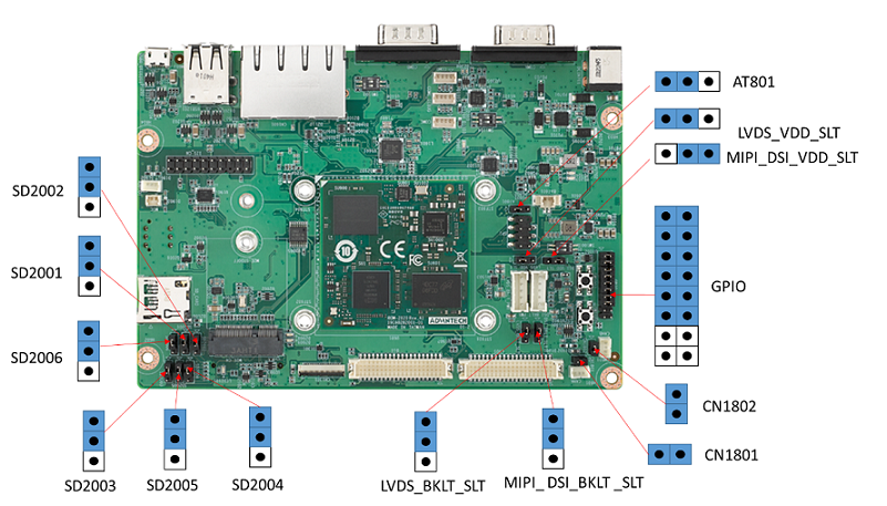
ROM-2820 接口布局圖 Board Dimension Layout
ROM-ED93 接口布局圖 Board Dimension Layout
主板内置插针式引脚排序方式 (Pin Header defination)
Internal I/O, Jummper/Switch List:
| Position | Description |
| AT801 | AT/ATX select header |
| AUDIO1 | Line Out Connector |
| BAT601 | Battery Connector |
| CN1301 | Camera FPC connector |
| CN1801 | CANA terminal resistor enable jumper |
| CN1802 | CANB terminal resistor enable jumper |
| CANA | CAN Bus Connector |
| CANB | CAN Bus Connector |
| COMA | RS232/422/485 |
| COMB | RS232/422/485 |
| COMC | COM A port wafer |
| COMD | COM D port wafer |
| COME_DEBUG | Debug console wafer |
| CN1601 | RJ45 1x2 |
| DCIN701 | 12V DCIN connector |
| DSI | DSI connector |
| DSI_BKLT_PWR | DSI blacklight wafer |
| DSI_BKLT_SLT | DSI blacklight power select |
| DSI_VDD_SLT | DSI VDD power select |
| GPIO | GPIO header |
| I2S_CN | Audio expander pin header |
| LVDS | LVDS connector |
| LVDS_BKLT_PWR | LVDS blacklight wafer |
| LVDS_BKLT_SLT | LVDS blacklight power select |
| LVDS_VDD_SLT | LVDS VDD power select |
| M2B_CN | M2 Key B connector |
| M2E_CN | M2 Key E connector |
| MIC | MIC Connector |
| SD_CARD | Micro SD slot |
| SD2001 | SDIO device select jumper |
| SD2002 | SDIO device select jumper |
| SD2003 | SDIO device select jumper |
| SD2005 | SDIO device select jumper |
| SD2004 | SDIO device select jumper |
| SD2006 | SDIO device select jumper |
| SIM | SIM card connector |
| SPI | SPI pin header |
| SW1001 | Boot select switch |
| SW1002 | Reset button |
| SW1003 | Power button |
| SW1104 | COMA UART setting switch |
| SW1103 | COMB UART setting switch |
| USB1201 | USB2.0 2x1 Connector |
| USB0_OTG1 | Micro USB Connector |
快速入門 (Quick Start)
系统下载 (OS Download)
- 'Linux系统 (Linux OS)'
Yocto 4.2: IoTGateway/BSP/Linux/iMX8/OS Support List 4.2 release ROM-2820 - ESS-WIKI (advantech.com.tw)
Linux 燒錄方法 (Linux Flash eMMC Method)
使用Flash tool 燒錄鏡像到eMMC (Flash image into eMMC by Flash Tools)
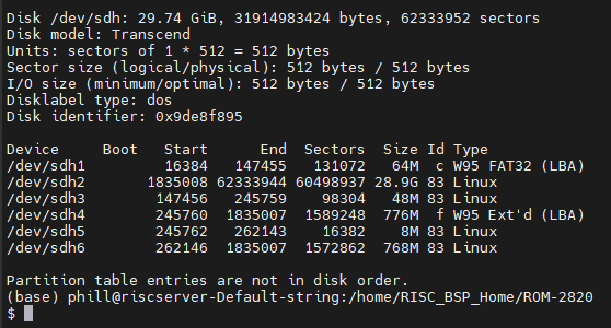
Step0: 檢查SD卡在Linux 環境的代號 (check SD card symbol in Linux system)
Step1: 創造一張可開機的SD 卡 (Create a bootable SD card)
Command :
sudo dd if=2820A1AIM36LIVD0042_iMX93_2G_2024-05-26.img of=/dev/sdh bs=1M conv=fsync

Step2: 將可開機的SD 卡插入底板SD卡卡槽(Plug the SD card into Carrier board 's SD card slot)
Step3: 確認開機選擇指撥開關
| SD boot: | 1 on , 2on |
| EMMC boot: | 1 off , 2 on |
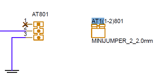
AT/ATX mode Jumper
| AT mode | 2&3 |
| ATX mode | 1&2 |
System ID : root
Password : 12345678
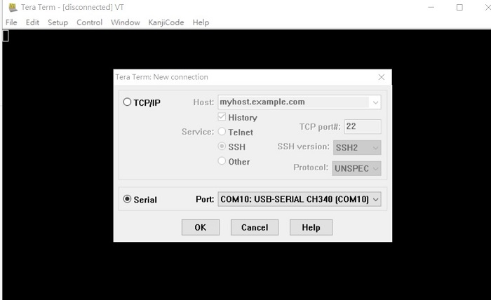
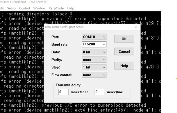
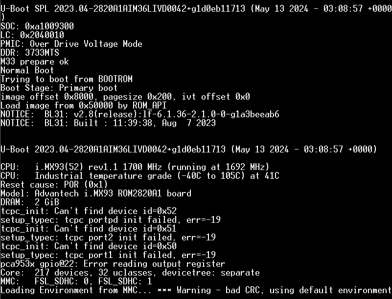
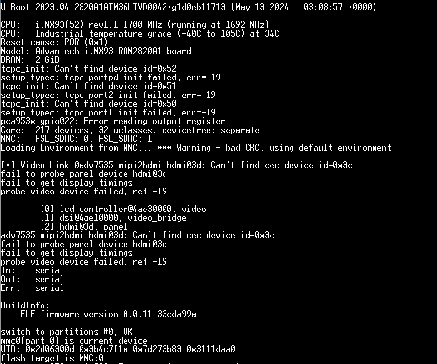
Step4:打開電源 和 終端機 (Turn on the Power & Terminal)
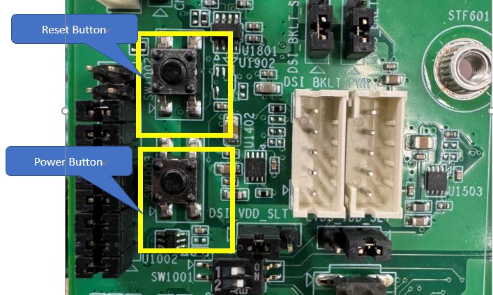
Step 5: 按下Power 開關 (Turn on Power , open terminal , then press the Power Button )
SW1003 : PWR_Button , SW1002: Reset_Button
Step6: 複製flash tool到U盤中, 解壓縮flash tools檔案,(copy to USB Disk, then unzip the flash tools file)(Test with 32G SD card)
複製檔案到U盤中 (Copy the flash file to USB Disk), 解壓縮flash tool到home目錄(Unzip the file to home)
- Format your USB Disk to ext2 format
Command : sudo mkfs.ext2 -F /dev/sdX
2. Unzip the flash file in your linux system
3. Copy the flash file into USB DISK
4. 進入flsah tool下的mk_inand資歷夾, 執行指令./mksd-linux.sh /dev/mmcblk0燒錄image到eMMC(Connect USB Disk to ROM-2820 system, extract the flash tool and browser to mk_inand folder and execute flash shell script "./mksd-linux.sh /dev/mmcblk0"
解壓縮後如果沒有mksd-linux.sh檔案, 可以到以下連結下載並複製到mk_inand資料夾下(If there is no mksd-linux.sh file in mk_inand directory. Please download from the link below and place it in mk_inand directory:
下載 mksd-linux.sh
| ROM-2820 | Device node |
| SD card | /dev/mmcblk1 |
| eMMC | /dev/mmcblk0 |
Step 7 . 移除SD card , 切換開機switch來設定成從eMMC開機(Romve SD card and Change boot switch to boot from eMMC. Reboot system).
| SD boot: | 1 on , 2on |
| EMMC boot: | 1 off , 2 on |
Debug 串口調試 (Debug port Setting)
以 Tera Term 为例介绍如何使用串口调试功能
Tera Term Tool
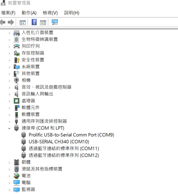
Check the Sriel port in Device Manager (查看PC端的串口号):
if you can not identify the Serial device , please check your serial driver.
Debug port connection (串口連接)
Log into Terminal Tool (进入串口调试终端):
Linux系统的基本使用(Linux System Basic Operating Method)
Recovery by UUU Tool 使用方法(Mirco USB Connection (OTG port))
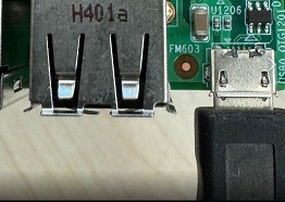
Connect Mirco USB cable to USB OTG port.
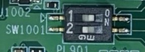
Change boot switch to "SW1001 " to boot from force recovery mode.
| Serial download: | 1on , 2 off |
Download uuu tool from link below:
Releases · nxp-imx/mfgtools (github.com)
The uuu verison we tested is 1.4.193: uuu
uuu (Universal Update Utility) for nxp imx chips -- libuuu_1.4.193-0-ge56424c
Perpare uboot and image files below:
1. Download uuu
Connect OTG to Ubuntu System(x86 PC) , make sure the device was identified
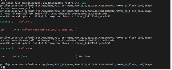
Type command below to flash eMMC:
# tar -xvzf 2820A1AIM36LIVD0042_iMX93_2G_flash_tool.tgz
# cd 2820A1AIM36LIVD0042_iMX93_2G_flash_tool/image/
# sudo ./uuu -b emmc_all imx-image-full-imx93rom2820a1-20240321094239.rootfs.wic
Display Setting (ROM-2820)
LVDS
Single Channel LVDS: G070VW01 (VDD: 3.3V, Backlight Power: 12V)
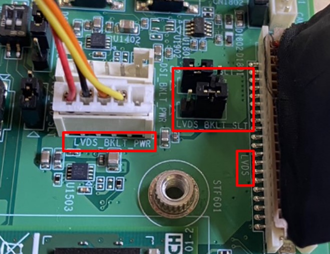
Step 1: Connect G070VW01 LVDS panel with the LVDS cable. Connect this to the LVDS. Connect the Backlight cable to LVDS_BKLT_PWR.
Step 2: Connect another 12V adapter to the DC-Jack on the backlight cable.
Step 3: Power on RSB-2820 and the extra 12V adapter.
Step 4: Press enter after boot. The system will stop at u-boot as demonstrated below, enter the command in red and press enter.
(LVDS_BPLT_SLT : 2&3 jumper short)
Hit any key to stop autoboot: 0
=> setenv fdtfile imx93-rom2820-a1-lvds.dtb
=> saveenv
=> boot
MIPI HDMI
Single Channel MIPI HDMI: (VDD: 3.3V, Backlight Power: 5V)
Step 1: Connect another 5V adapter to the DC-Jack on the backlight cable.
Step 2: Power on RSB-2820 and the extra 5V adapter.
Step 3: Press enter after boot. The system will stop at u-boot as demonstrated below, enter the command in red and press enter.
(LVDS_BPLT_SLT : 2&3 jumper short)
Hit any key to stop autoboot: 0
=> setenv fdtfile imx93-rom2820-a1.dtb
=> saveenv
=> boot
MIPI DSI
Single Channel LVDS: G101UAN02.0 (VDD: 3.3V, Backlight Power: 12V)
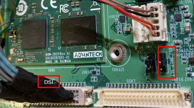
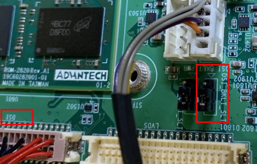
Step 1: Connect G101UAN02.0 LVDS panel with the LVDS cable. Connect this to theLVDS. Connect the Backlight cable to DSI_BKLT_PWR.
Step 2: Connect another 12V adapter to the DC-Jack on the backlight cable.
Step 3: Power on RSB-2820 and the extra 12V adapter.
Step 4: Press enter after boot. The system will stop at u-boot as demonstrated below, enter the command in red and press enter.
(DSI_BKLT_SLT: 2&3 jumper short)
Hit any key to stop autoboot: 0
=> setenv fdtfile imx93-rom2820-a1-auog101uan02.dtb
=> saveenv
=> boot
Audio(Audio Testing Methid)
Step 1: Check audio codec
# cat /proc/asound/cards
0 [sgtl5000 ]: sgtl5000 - sgtl5000 sgtl5000
Step 2: Audio codec (sgtl5000):
- Set MIC and headphone:
# amixer set Mic 100%
# amixer set Headphone 100%
Record and playback:
Record
# arecord -D plughw:0,0 -r 16000 -f S16_LE ./f-16000.wav
Playback
# aplay -D plughw:0,0 f-16000.wav
M.2 WiFi/BT測試方法(M.2 WiFi/BT Testing Method)
- Test Wi-Fi with NXP IW-612 Module (SDIO Interface)
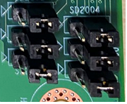
Step 1: Switch jumper SD2001~SD2006(2&3 jumper short)
Step 2: Press enter after boot. The system will stop at u-boot, and change dtb file by below command.
# setenv fdtfile imx93-rom2820-a1-m2-sdio.dtb
# saveenv
# boot
Step 3: Install driver by below command.
Step 4: WIFI test command.
#ifconfig mlan0 up
#wpa_passphrase ${SSID} ${PASSWORD} > /tmp/wpa.conf
#wpa_supplicant -BDwext -imlan0 -c/tmp/wpa.conf
#udhcpc -b -i mlan0
Test Bluetooth with NXP IW-612 Module (UART Interface):
Step 1: Please refer to the 3.3.1 step 1.
Step 2: Please refer to the 3.3.1 step 2.
Step 3: Please refer to the 3.3.1 step 3.
Step 4: Bluetooth test command.
# modprobe btnxpuart
# hciconfig hci0 up
# bluetoothctl
# discoverable on
# pairable on
# scan on
[NEW] FC:18:3C:8D:75:F4 myphone
# scan off
# pair FC:18:3C:8D:75:F4
# connect FC:18:3C:8D:75:F4
- Test 4G with EWM-C401CQE01 Module (UART Interface)
Step1 :You need to connect two antennas.
Step2 : Uboot command
- setenv fdtfile imx93-rom2820-a1-m2-sdio.dtb
- saveenv
- reset
Step 2: Install driver by below command.
Step3: 4G test command.
# stty -F /dev/ttyUSB1 speed 115200 -echo
# cat /dev/ttyUSB1 &
# echo "AT+CSQ" > /dev/ttyUSB1

Console message:
AT+CSQ

+CSQ: 25,99

OK
# pppd connect 'chat -v -s -t 10 "" "AT" "" "ATDT*99#" "CONNECT" ""' user username password password /dev/ttyUSB2 460800 nodetach crtscts debug usepeerdns defaultroute &
# ping 8.8.8.8
64 bytes from 8.8.8.8: icmp_seq=1 ttl=56 time=222 ms
Serial Port測試方法(Serial Testing Method)(COM A/C)
RS-232
- RS-232 Loopback Test (eg. COMA: ttyLP0):
Step 1:. Connect loopback with COMA(ttyLP4)&COMB(ttyLP5)
Step 2: Run test command.
# stty -F /dev/ttyLP4 -echo -onlcr 115200
# cat /dev/ttyLP4 &
# echo "Serial Port Test" > /dev/ttyLP4
RS-485
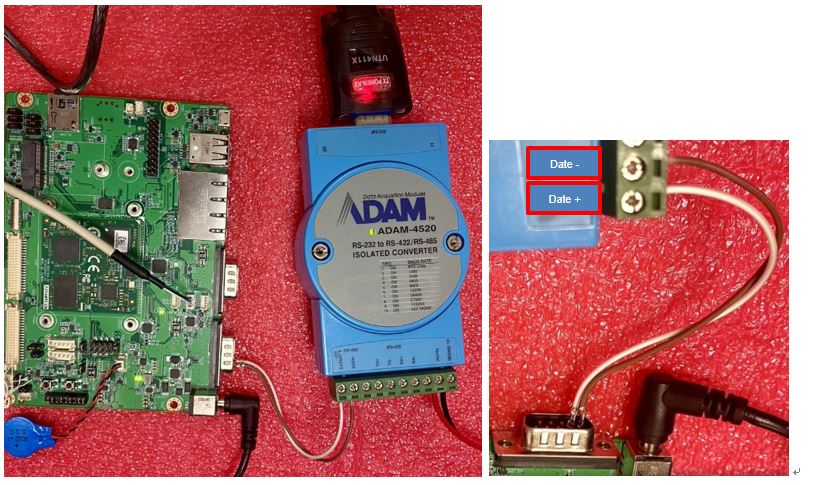
RS-485 Test:
Step 1: Test RS-485 with Adam-4520. Connect Adam-4520 with COMA with DB9 as the following(COMA(ttyLP4)&COMB(ttyLP5))
Adam-4520 RX- <-->ROM-2820 COMA DB9 Pin 1,
Adam-4520 RX+ <-->ROM-2820 COMA DB9 Pin 2,
Adam-4520 TX- <-->ROM-2820 COMB DB9 Pin 1,
Adam-4520 TX+ <--> ROM-2820 COMB DB9 Pin 2
Step 3: Run below command:
# cat /dev/ttyLP0 &
# echo "Serial Test" > /dev/ttyLP0
Step 2 :Create the following file and save it as rs485.sh
#!/bin/sh

i2cset -y -f 4 0x21 0x00 0x10
i2cset -y -f 4 0x21 0x01 0x01
i2cset -y -f 4 0x21 0x02 0xdf
i2cset -y -f 4 0x21 0x03 0xfd
i2cset -y -f 4 0x21 0x04 0x00
i2cset -y -f 4 0x21 0x05 0x00
i2cset -y -f 4 0x21 0x06 0xcf
i2cset -y -f 4 0x21 0x07 0xfc
Step 3: Run below command:
# sudo chmod 775 rs485.sh
# ./rs485.sh
# stty -F /dev/ttyLP4 -echo -onlcr 115200
# cat /dev/ttyLP4 &
# echo "Serial Port Test" > /dev/ttyLP4
Step 4: You need to open two terminals: one to connect to the debug port of the ROM2820, and the other to connect to the Adam-4520.
Step 5:You can send data from the ROM2820's debug port to the Adam-4520, and you can also input text from the Adam-4520's terminal using the keyboard so that the ROM2820's debug port can receive it.
I2C測試方法(I2C Testing Method)
Step 1: Test command
# i2cdetect -l
i2c-0 i2c 44340000.i2c I2C adapter
i2c-1 i2c 44350000.i2c I2C adapter
i2c-2 i2c 42530000.i2c I2C adapter
i2c-4 i2c 426b0000.i2c I2C adapter
i2c-7 i2c 426e0000.i2c I2C adapter
RS-422
RS-422 Test
USB測試方法(USB Testing Method)
USB disk test (USB 2.0)
Step 1:Issue the following command (lsusb -t) after inserting a USB disk into the USB 2.0 port to check if the USB device is listed.
Step 2: Test (eg. if usb disk is /dev/sda)
# dd if=/dev/urandom of=data bs=1 count=1024
# dd if=/dev/sda of=backup bs=1 count=1024 skip=4096 # dd if=data of=/dev/sda bs=1 seek=4096
# dd if=/dev/sda of=data1 bs=1 count=1024 skip=4096 # diff data data1
# dd if=backup of=/dev/sda bs=1 seek=4096
RTC測試方法(RTC Testing Method)
Step 1: Set system time to current, then write to RTC
Step 2: Set one incorrect time, then read time from RTC to verify
Step 3: Restore the RTC time to system time
root@imx93rom2820a1:~# date
eMMC/SD測使方法(eMMC/SD Testing Method)
Device Routes
eMMC: /dev/mmcblk0
SD: /dev/mmcblk2
Test (eg. emmc)
Step 1: Test command:
# dd if=/dev/mmcblk0 of=backup bs=1 count=1024 skip=4096
# dd if=data of=/dev/mmcblk0 bs=1 seek=4096
# dd if=/dev/mmcblk0 of=data1 bs=1 count=1024 skip=4096
# diff data data1
# dd if=backup of=/dev/mmcblk0 bs=1 seek=4096
乙太網路使用方法(Ethernent Testing Method)
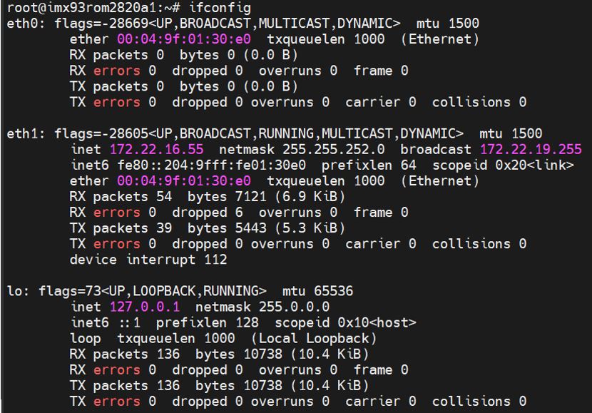
Command : ifconfig
Command: Ping - I eth1 8.8.8.8 or Ping - I eth0 8.8.8.8
GPIO使用方法(GPIO Operating Method)
GPIO pin:
| CPU pin to GPIO | GPIO 1101 | Number |
| GPIO1(shared pin) | 1 | 496 |
| GPIO2 | 2 | 497 |
| GPIO3 | 3 | 498 |
| GPIO4 | 4 | 499 |
| GPIO5 | 5 | 500 |
| GPIO6 | 6 | 501 |
| GPIO7 | 7 | 502 |
| GPIO8 | 8 | 503 |
| GPIO9 | 9 | 504 |
| GPIO10 | 10 | 505 |
| GPIO11 | 11 | 506 |
| GPIO12 | 12 | 507 |
GPIO loop test:
Connect GPIO pin#3 and GPIO pin#4

root@imx93rom2820a1:/# echo 498 > /sys/class/gpio/export

root@imx93rom2820a1:/# echo 499 > /sys/class/gpio/export

root@imx93rom2820a1:/# echo out > /sys/class/gpio/gpio498/direction

root@imx93rom2820a1:/# echo in  > /sys/class/gpio/gpio499/direction

root@imx93rom2820a1:/#cat /sys/class/gpio/gpio498/value

0

root@imx93rom2820a1:/# echo 1 > /sys/class/gpio/gpio498/value

root@imx93rom2820a1:/# cat /sys/class/gpio/gpio498/value

1
Connect GPIO pin#5 and GPIO pin #6

root@imx93rom2820a1:/# echo 500 > /sys/class/gpio/export

root@imx93rom2820a1:/# echo 501 > /sys/class/gpio/export

root@imx93rom2820a1:/# echo out > /sys/class/gpio/gpio500/direction

root@imx93rom2820a1:/# echo in  > /sys/class/gpio/gpio501/direction

root@imx93rom2820a1:/# cat /sys/class/gpio/gpio500/value

0

root@imx93rom2820a1:/# echo 1 > /sys/class/gpio/gpio500/value

root@imx93rom2820a1:/# cat /sys/class/gpio/gpio501/value

1
Connect GPIO pin#7 and GPIO pin#8

root@imx93rom2820a1:/# echo 502 > /sys/class/gpio/export

root@imx93rom2820a1:/# echo 503 > /sys/class/gpio/export

root@imx93rom2820a1:/# echo out > /sys/class/gpio/gpio502/direction

root@imx93rom2820a1:/# echo in  > /sys/class/gpio/gpio503/direction

root@imx93rom2820a1:/# cat /sys/class/gpio/gpio502/value

0

root@imx93rom2820a1:/# echo 1 > /sys/class/gpio/gpio502/value

root@imx93rom2820a1:/# cat /sys/class/gpio/gpio503/value

1
Connect GPIO pin#9 and GPIO pin#10

root@imx93rom2820a1:/# echo 504 > /sys/class/gpio/export

root@imx93rom2820a1:/# echo 505 > /sys/class/gpio/export

root@imx93rom2820a1:/# echo out > /sys/class/gpio/gpio504/direction

root@imx93rom2820a1:/# echo in  > /sys/class/gpio/gpio505/direction

root@imx93rom2820a1:/# cat /sys/class/gpio/gpio504/value

0

root@imx93rom2820a1:/# echo 1 > /sys/class/gpio/gpio504/value

root@imx93rom2820a1:/# cat /sys/class/gpio/gpio505/value

1
Connect GPIO pin#11 and GPIO pin#12

root@imx93rom2820a1:/# echo 506 > /sys/class/gpio/export

root@imx93rom2820a1:/# echo 507 > /sys/class/gpio/export

root@imx93rom2820a1:/# echo out > /sys/class/gpio/gpio506/direction

root@imx93rom2820a1:/# echo in  > /sys/class/gpio/gpio507/direction

root@imx93rom2820a1:/# cat /sys/class/gpio/gpio507/value

0

root@imx93rom2820a1:/# echo 1 > /sys/class/gpio/gpio506/value

root@imx93rom2820a1:/# cat /sys/class/gpio/gpio507/value

1
Camera使用方法(Camera Testing Method)
MIPI-CSI0 (Tested with OV5640 + mini-SAS to MIPI-CSI Cable): OV5640 CSI (CN701): Connect OV5640 camera to EG-55 CAM3
Step 1: Take pictures
Step 2: View on panel
PWM測試方法(PWM Testing Method)
TBD
CAN Bus
通用方法(General Method)
查看CPU温度(Check CPU Temperature)
39850
root@imx93rom2820a1:/home#
查看内存容量(Check Memory Capacity)
total used free shared buff/cache available
Mem: 1.9Gi 197Mi 1.6Gi 9.6Mi 215Mi 1.7Gi
Swap: 0B 0B 0B
root@imx93rom2820a1:/home#
查看存储容量(Check Storage Capacity)
Filesystem Type Size Used Avail Use% Mounted on
/dev/root ext4 6.1G 3.5G 2.4G 60% /
devtmpfs devtmpfs 716M 4.0K 716M 1% /dev
tmpfs tmpfs 973M 0 973M 0% /dev/shm
tmpfs tmpfs 390M 9.5M 380M 3% /run
tmpfs tmpfs 4.0M 0 4.0M 0% /sys/fs/cgroup
tmpfs tmpfs 973M 4.0K 973M 1% /tmp
tmpfs tmpfs 973M 196K 973M 1% /var/volatile
/dev/mmcblk0p1 vfat 84M 33M 51M 39% /run/media/boot-mmcblk0p1
tmpfs tmpfs 195M 0 195M 0% /run/user/0
root@imx93rom2820a1:/home#
設置RTC (RTC Setting)
查看系統時間 (Check the system)
[ 41.402592] kauditd_printk_skb: 6 callbacks suppressed
[ 41.402611] audit: type=1334 audit(45.332:16): prog-id=15 op=LOAD
[ 41.417884] audit: type=1334 audit(45.344:17): prog-id=16 op=LOAD
Local time: Thu 1970-01-01 00:00:46 UTC
Universal time: Thu 1970-01-01 00:00:46 UTC
RTC time: Thu 1970-01-01 00:00:45 <----- Real-Time Clock,RTC
Time zone: Universal (UTC, +0000) <------ Time zone 目前
System clock synchronized: no
NTP service: active
RTC in local TZ: no
           Local time: Fri 2024-05-03 09:07:42 CST
            Universal time: Fri 2024-05-03 01:07:42 UTC
                 RTC time: Fri 2024-05-03 09:07:42
                 Time zone: Asia/Taipei (CST, +0800)
 System clock synchronized: yes
               NTP service: active
               RTC in local TZ: yes