Difference between revisions of "IoTGateway/Net HAL Simulator"
Fred.chang (talk | contribs) (→Interface description) |
Fred.chang (talk | contribs) (→Programmable mode) |
||
| (8 intermediate revisions by one other user not shown) | |||
| Line 11: | Line 11: | ||
Sensor_Default_Info="n:Temp, u:Cel" | Sensor_Default_Info="n:Temp, u:Cel" | ||
Sensor_Default_Value="v:(##), min:0, max:100" | Sensor_Default_Value="v:(##), min:0, max:100" | ||
| − | Sensor_Default_Trigger_Mode= | + | Sensor_Default_Trigger_Mode="Edge" |
*The Sensor_Type indicates the kind of sensor. | *The Sensor_Type indicates the kind of sensor. | ||
*The Sensor_Default_Info has two values, name(n) and unit(u). | *The Sensor_Default_Info has two values, name(n) and unit(u). | ||
*The Sensor_Default_Value has three values, value(v), minimum(min) and maximum(max). The sign “(##)” means a programmable value which is generated by simulator, and it will be explained in chapter programmable value. | *The Sensor_Default_Value has three values, value(v), minimum(min) and maximum(max). The sign “(##)” means a programmable value which is generated by simulator, and it will be explained in chapter programmable value. | ||
*The Sensor_Default_Trigger_Mode has an alternative option, Edge or Level. Edge is reported by triggering, and Level is reported per second. | *The Sensor_Default_Trigger_Mode has an alternative option, Edge or Level. Edge is reported by triggering, and Level is reported per second. | ||
| + | |||
==Interface description== | ==Interface description== | ||
This file is placed in a directory named by Communication_Type like “wsn” and filename is fixed to “@interface.ini”. The type of the interface on gateway was defined in it like Wifi, WSN, Zeebig, Bluetooth and so on. Those had some important values like mac or uuid. The form is shown below. | This file is placed in a directory named by Communication_Type like “wsn” and filename is fixed to “@interface.ini”. The type of the interface on gateway was defined in it like Wifi, WSN, Zeebig, Bluetooth and so on. Those had some important values like mac or uuid. The form is shown below. | ||
| Line 22: | Line 23: | ||
[Interface] | [Interface] | ||
| − | Interface_Name=" | + | Interface_Name="WSN" |
Interface_Number=0 | Interface_Number=0 | ||
Interface_Id="0001852CF4B7B0E8" | Interface_Id="0001852CF4B7B0E8" | ||
| Line 32: | Line 33: | ||
**The Interface_Number is the index of this interface in system. | **The Interface_Number is the index of this interface in system. | ||
**The Interface_Id is the mac or the uuid of interface. | **The Interface_Id is the mac or the uuid of interface. | ||
| − | **The Interface_Health is the calculated result of health. | + | **The Interface_Health is the calculated result of health or a fake number. |
==Virtual mote description== | ==Virtual mote description== | ||
| Line 47: | Line 48: | ||
Sensor_Info="n:Environment CO2" | Sensor_Info="n:Environment CO2" | ||
Sensor_Value="v:25, min:0, max:50" | Sensor_Value="v:25, min:0, max:50" | ||
| − | Sensor_Trigger_Mode= | + | Sensor_Trigger_Mode="Edge" |
Sensor_Type="Temperature" | Sensor_Type="Temperature" | ||
Sensor_Info="n:Room Temp" | Sensor_Info="n:Room Temp" | ||
Sensor_Value="min:0, max:100" | Sensor_Value="min:0, max:100" | ||
| − | Sensor_Trigger_Mode= | + | Sensor_Trigger_Mode="Level@3" |
*Sensor_Product is a user-defined name. | *Sensor_Product is a user-defined name. | ||
| Line 59: | Line 60: | ||
*Sensor_Element_Size indicates the number of sensor. | *Sensor_Element_Size indicates the number of sensor. | ||
*Sensor_Type、Sensor_Info、Sensor_Value are the same as Sensor support list. If the value is not defined in this scope, the default value in Sensor support list will be adopted. | *Sensor_Type、Sensor_Info、Sensor_Value are the same as Sensor support list. If the value is not defined in this scope, the default value in Sensor support list will be adopted. | ||
| − | *Sensor_Trigger_Mode has two choices, Edge and Level. Edge is triggered if value is changed. Level is triggered per | + | *Sensor_Trigger_Mode has two choices, Edge and Level. Edge is triggered if value is changed. Level is triggered per customize sec, but it is also triggered by that value is changed. |
=Programmable value= | =Programmable value= | ||
| Line 66: | Line 67: | ||
If there are no other words in the center of the sign like (##), It is the random mode. The value will updated by random value per second. | If there are no other words in the center of the sign like (##), It is the random mode. The value will updated by random value per second. | ||
==Programmable mode== | ==Programmable mode== | ||
| − | The syntax is “(#[second]@[value]- [second]@[value]-…and so on#)” like “(#3@5-7@13-9@1#)”. The meaning of | + | The syntax is “(#[second]@[value]- [second]@[value]-…and so on#)” like “(#3@5-7@13-9@1#)”. The meaning of c is shown below chart. The latest second word like 9+1=10 is the period of the code, and the value of the zero second is equal to the value of the latest second. In other words, “(#3@5-7@13-9@1#)” is equal to “(#0@1-3@5-7@13-9@1#)”. |
[[File:Mote simulator random value.png]] | [[File:Mote simulator random value.png]] | ||
Latest revision as of 04:02, 16 August 2016
Contents
Introduction
It is difficult to allocate abundant sensors to verify IoT system, so this simulator is used to generate many virtual configurable motes(be a mote manager) to detect unknown bugs between gateway and cloud. In some scenarios, we can use it to simulate a developing sensor and analyze the interaction between them to increase our system compatibility or speed up our development progress. We can also release the simulator to help our customer speedup the development.
File structure and placement
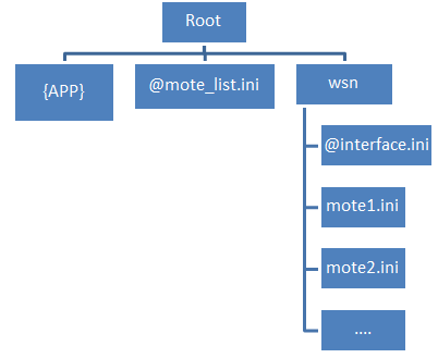
Each ini file in wsn directory is a unique senhub to descript internal sensor information, and the file @mote_list.ini is the prototype list of sensor information.

Configure file
Sensor prototype list
This file is placed in execute path and its filename is a static name “@mote_list.ini”. Many kinds of sensors were defined in this file, and those would be used to match the one inside a virtual mote’s ini to get default values and fundamental parameters. The form is shown below.
Sensor_Type="Temperature"
Sensor_Default_Info="n:Temp, u:Cel"
Sensor_Default_Value="v:(##), min:0, max:100"
Sensor_Default_Trigger_Mode="Edge"
- The Sensor_Type indicates the kind of sensor.
- The Sensor_Default_Info has two values, name(n) and unit(u).
- The Sensor_Default_Value has three values, value(v), minimum(min) and maximum(max). The sign “(##)” means a programmable value which is generated by simulator, and it will be explained in chapter programmable value.
- The Sensor_Default_Trigger_Mode has an alternative option, Edge or Level. Edge is reported by triggering, and Level is reported per second.
Interface description
This file is placed in a directory named by Communication_Type like “wsn” and filename is fixed to “@interface.ini”. The type of the interface on gateway was defined in it like Wifi, WSN, Zeebig, Bluetooth and so on. Those had some important values like mac or uuid. The form is shown below.
Communication_Type="WSN"

[Interface]
Interface_Name="WSN"
Interface_Number=0
Interface_Id="0001852CF4B7B0E8"
Interface_Health="90"
- The Communication_Type indicates the type of interface like Wifi, BT, Zigbee and so on.
- In the Interface block, the interface has four parameters.
- The Interface_Name is the name of interface.
- The Interface_Number is the index of this interface in system.
- The Interface_Id is the mac or the uuid of interface.
- The Interface_Health is the calculated result of health or a fake number.
Virtual mote description
We can make many description files to simulate motes. Those files are placed in a directory named by Communication_Type like “wsn”, and all files in it will be recognized into the mote description. The mote description file can include many sensors. In other words, a mote means a sensor hub. The example is shown below.
[SensorHub]
Sensor_Product="WISE1020"
Sensor_Id="0001000EC6F0F832"
Sensor_Connect_To="0001000EC6F0F831"

[Sensor]
Sensor_Element_Size="2"

Sensor_Type="CO2"
Sensor_Info="n:Environment CO2"
Sensor_Value="v:25, min:0, max:50"
Sensor_Trigger_Mode="Edge"

Sensor_Type="Temperature"
Sensor_Info="n:Room Temp"
Sensor_Value="min:0, max:100"
Sensor_Trigger_Mode="Level@3"
- Sensor_Product is a user-defined name.
- Sensor_Id is mac or uuid.
- Sensor_Connect_To is a list of mac connected to this mote.
- Sensor_Element_Size indicates the number of sensor.
- Sensor_Type、Sensor_Info、Sensor_Value are the same as Sensor support list. If the value is not defined in this scope, the default value in Sensor support list will be adopted.
- Sensor_Trigger_Mode has two choices, Edge and Level. Edge is triggered if value is changed. Level is triggered per customize sec, but it is also triggered by that value is changed.
Programmable value
The sign (##) means it’s a programmable code, there are two methods which is shown below.
Random mode
If there are no other words in the center of the sign like (##), It is the random mode. The value will updated by random value per second.
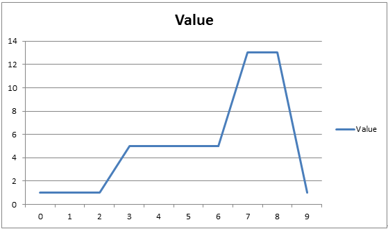
Programmable mode
The syntax is “(#[second]@[value]- [second]@[value]-…and so on#)” like “(#3@5-7@13-9@1#)”. The meaning of c is shown below chart. The latest second word like 9+1=10 is the period of the code, and the value of the zero second is equal to the value of the latest second. In other words, “(#3@5-7@13-9@1#)” is equal to “(#0@1-3@5-7@13-9@1#)”.
