Difference between revisions of "Modbus Handler v1.0"
| Line 23: | Line 23: | ||
| − | <span style="font-size:larger;">'''<u> | + | <span style="font-size:larger;">'''<u>Config for the modbus TCP devices:</u>'''</span> |
<span style="font-size:larger;">Protocol=Modbus_TCP</span> | <span style="font-size:larger;">Protocol=Modbus_TCP</span> | ||
| Line 31: | Line 31: | ||
<span style="font-size:larger;">ClientPort=(Port of Modbus TCP devices)</span><span style="font-size:large;"> </span> | <span style="font-size:larger;">ClientPort=(Port of Modbus TCP devices)</span><span style="font-size:large;"> </span> | ||
| − | '''<span style="font-size:larger;"> | + | '''<span style="font-size:larger;">Example:</span>''' |
<pre>[Platform] | <pre>[Platform] | ||
Name=WISE-4012E | Name=WISE-4012E | ||
| Line 49: | Line 49: | ||
| − | <span style="font-size:larger;">'''<u> | + | <span style="font-size:larger;">'''<u>Config for the modbus RTU devices:</u>'''</span> |
<span style="font-size:larger;">Protocol=Modbus_RTU</span> | <span style="font-size:larger;">Protocol=Modbus_RTU</span> | ||
| Line 88: | Line 88: | ||
<span style="font-size:large;">2.3 Set Modbus devices detail configuration.</span> | <span style="font-size:large;">2.3 Set Modbus devices detail configuration.</span> | ||
| − | '''<span style="font-size:larger;"> | + | '''<span style="font-size:larger;">Example for Coils:</span>''' |
<pre>[Coils] | <pre>[Coils] | ||
numberOfB=3 | numberOfB=3 | ||
| Line 98: | Line 98: | ||
| − | '''<span style="font-size:larger;"> | + | '''<span style="font-size:larger;">Example for Discrete Inputs:</span>''' |
<pre>[Discrete Inputs] | <pre>[Discrete Inputs] | ||
numberOfIB=3 | numberOfIB=3 | ||
| Line 104: | Line 104: | ||
IB1=1,Switch1 | IB1=1,Switch1 | ||
IB2=2,Switch2</pre> | IB2=2,Switch2</pre> | ||
| − | |||
| − | |||
= <span style="font-size:x-large;">EdgeSense Linux Docker version</span> = | = <span style="font-size:x-large;">EdgeSense Linux Docker version</span> = | ||
Revision as of 11:12, 6 August 2018
Contents
Introduction
Modbus enables communication among many devices connected to the same network, for example, a system that measures temperature and humidity and communicates the results to a computer. Modbus is often used to connect a supervisory computer with a remote terminal unit (RTU) in supervisory control and data acquisition (SCADA) systems.
Many of the data types are named from its use in driving relays: a single-bit physical output is called a coil, and a single-bit physical input is called a discrete input or a contact.
Modbus Service is a Windows/Linux system service for WISE Agent to read sensor data from Modbus device or write data into Modbus device. After sensor ata are acquired, WISE Agent will upload the data to the WISE-PaaS Cloud.
Configuration
1. Open File Explorer and change target folder to the Modbus Handler installation folder.
2. Open and edit the file Mobus_Handler.ini
2.1 Give a Name for the platform.
2.2 Set the Protocol.
Config for the modbus TCP devices:
Protocol=Modbus_TCP
ClientIP=(IP address of Modbus TCP devices)
ClientPort=(Port of Modbus TCP devices)
Example:
[Platform]
Name=WISE-4012E
Protocol=Modbus_TCP
ClientIP=127.0.0.1
ClientPort=502
UnitID=1

Interval=3
#Interval: The time delay between two modbus access round in second.
Delay=0
#Delay: The time delay between two modbus access in millisecond.
#Delay=0 means no delay.
Log=0
Config for the modbus RTU devices:
Protocol=Modbus_RTU
SlavePort=(The serial port's device node of the Gateway which connect to Modbus RTU devices)
Baud=(The baud rate for the serial port to communicate with Modbus RTU device)
Parity=(The parity of the serial port)
DataBits=(The data bits of the serial port)
StopBits=(The stop bits of the serial port)
Example:
[Platform]
Name=EKI-XXXX
Protocol=Modbus_RTU
SlavePort=COM1
Baud=19200
Parity=None
DataBits=8
StopBits=1
SlaveID=1

Interval=3
#Interval: The time delay between two modbus access round in second.
Delay=0
#Delay: The time delay between two modbus access in millisecond.
#Delay=0 means no delay.
Log=0
2.3 Set Modbus devices detail configuration.
Example for Coils:
[Coils]
numberOfB=3
B0=0,LED0
B1=1,LED1
B2=2,LED2
Example for Discrete Inputs:
[Discrete Inputs]
numberOfIB=3
IB0=0,Switch0
IB1=1,Switch1
IB2=2,Switch2
EdgeSense Linux Docker version
How to config Modbus Service and Restart Service
$cd ${Installed path}/Installer/packages/Plugins/docker-edgesense-image-x86/EdgeSense/EService-Modbus/config
$sudo vim Modbus_Handler.ini
$sudo docker restart service-modbus
Application Case
ADAM-4117 8-channel Analog Input Module
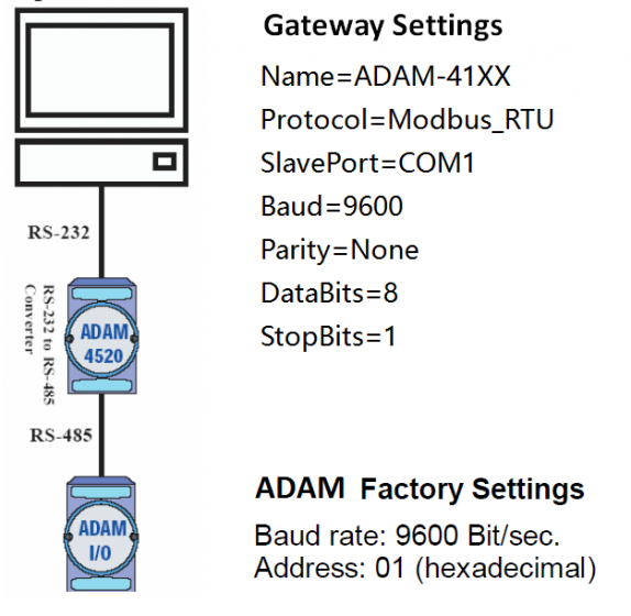
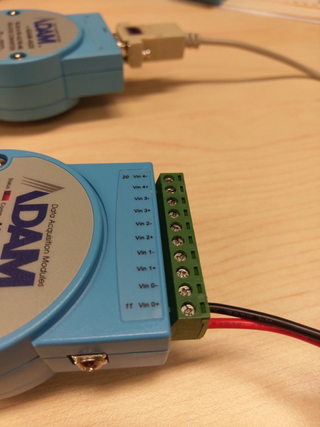
1. H.W. Environment & Configuration
2. Setup Modbus register from ADAM utility: AdamApax .NET Utility
2.1 Download AdamApax .NET Utility from URL http://support.advantech.com/Support/DownloadSRDetail_New.aspx?SR_ID=1-2AKUDB&Doc_Source=Download and install it to your Gateway.
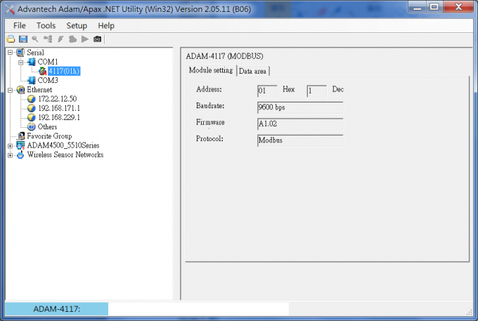
2.2 Launch AdamApax .NET Utility, select COM port which ADAM module is connected, right click on the COM port you selected and click "Search Device" to detect your ADAM-4117.
2.3 After ADAM-4117 appeared, click on it to check its settings or change the default settings for your H.W. configuration.
2.4 Provide a stable 12V voltage power to Vin0.
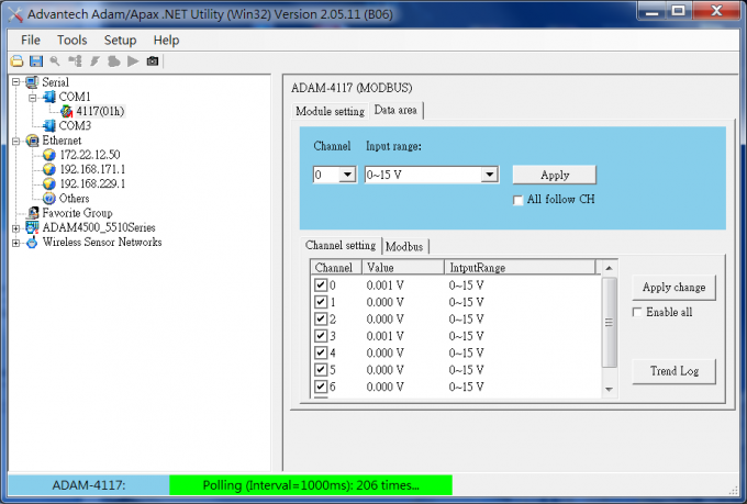
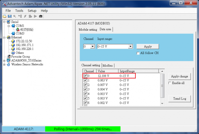
2.5 Check the value of Channel 0 from AdamApax .NET Utility, the value of Vin0 is 12.108V.
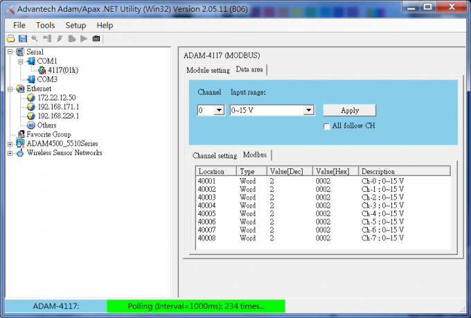
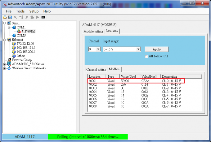
2.6 Check the value of Modbus Location 40001 from AdamApax .NET Utility, the value is 52900. ( 12.108 / 15 * 65536 = 52900.66 )
3. Gateway Modbus_Handler configuration
3.1 Edit Modbus_Handler.ini for the ADAM's configuration.
[Platform]
Interval=1
#Interval: The time delay between two modbus access round in second.
Delay=0
#Delay: The time delay between two modbus access in millisecond.
#Delay=0 means no delay.
Log=0

Name=ADAM-4117
Protocol=Modbus_RTU
SlavePort=COM1
Baud=9600
Parity=None
DataBits=8
StopBits=1
SlaveID=1
3.2 Edit Modbus_Handler.ini for ADAM-4117 modbus location configuration.
[Holding Registers]
numberOfR=3
R0=0,Vin0,0,65535,1,V,0,""
R1=1,Vin1,0,65535,1,V,0,""
R2=2,Vin2,0,65535,1,V,0,""

;tag = offset, name, min, max, precision, unit, data type, lua script

;tag    Base Address
;B    00001-->Coils
;IB    10001-->Discrete Inputs
;IR    30001-->Input Registers
;R    40001-->Holding Registers

;data type
;0->16-bit operation
;1->32-bit float no swap
;2->32-bit float byte and word swap
;3->32-bit float byte swap
;4->32-bit float word swap
;5->32-bit unsigned int no swap
;6->32-bit unsigned int word swap
;7->32-bit signed int no swap
;8->32-bit signed int word swap
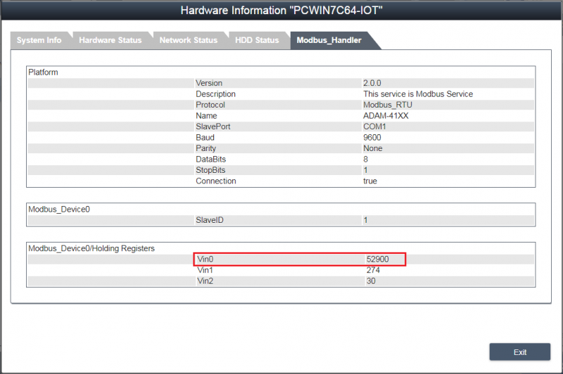
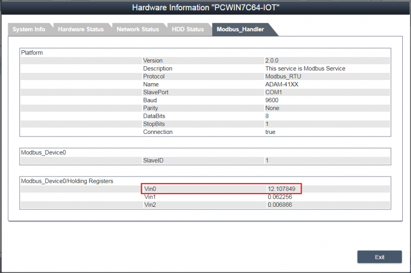
3.2 Restart WISE Agent service from Task Manager, login RMM 3.3 to check the values that ADAM-4117 and Gateway uploaded.
3.3 Use Lua convert function to transfer modbus value to voltage value, open Modbus_Device0.ini and give Vin0~Vin2 Lua scripts as "modbus_val*15/65536".
[Holding Registers]
numberOfR=3
R0=0,Vin0,0,15,1,V,0,"modbus_val*15/65536"
R1=1,Vin1,0,15,1,V,0,"modbus_val*15/65536"
R2=2,Vin2,0,15,1,V,0,"modbus_val*15/65536"

;tag = offset, name, min, max, precision, unit, data type, lua script
3.4 Login RMM 3.3 again to check the values that ADAM-4117 and Gateway uploaded, the value is already converted to voltage value.
