Difference between revisions of "Modbus Service"
| Line 177: | Line 177: | ||
<span style="font-size: medium;">1. DeviceInfo session:</span> | <span style="font-size: medium;">1. DeviceInfo session:</span> | ||
| − | |||
<span style="font-size: medium;"> [DeviceInfo]</span> | <span style="font-size: medium;"> [DeviceInfo]</span> | ||
| Line 194: | Line 193: | ||
<span style="font-size:medium;"> Bn: The sensors definitation of Coils.</span> | <span style="font-size:medium;"> Bn: The sensors definitation of Coils.</span> | ||
| − | |||
<span style="font-size:medium;">3. Discrete Inputs session</span> | <span style="font-size:medium;">3. Discrete Inputs session</span> | ||
| − | |||
<span style="font-size:medium;"> [Discrete Inputs]</span> | <span style="font-size:medium;"> [Discrete Inputs]</span> | ||
| Line 206: | Line 203: | ||
<span style="font-size:medium;"> IBn: The sensors definitation of Descrete Inputs.</span> | <span style="font-size:medium;"> IBn: The sensors definitation of Descrete Inputs.</span> | ||
| − | |||
<span style="font-size:medium;">4. Holding Registers session</span> | <span style="font-size:medium;">4. Holding Registers session</span> | ||
| − | |||
<span style="font-size:medium;"> [Holding Registers]</span> | <span style="font-size:medium;"> [Holding Registers]</span> | ||
| Line 218: | Line 213: | ||
<span style="font-size:medium;"> Rn: The sensors definitation of Holding Registers.</span> | <span style="font-size:medium;"> Rn: The sensors definitation of Holding Registers.</span> | ||
| − | |||
<span style="font-size:medium;">5. Input Registers session</span> | <span style="font-size:medium;">5. Input Registers session</span> | ||
| − | |||
<span style="font-size:medium;"> [Input Registers]</span> | <span style="font-size:medium;"> [Input Registers]</span> | ||
| Line 230: | Line 223: | ||
<span style="font-size:medium;"> IRn: The sensors definitation of Input Registers.</span> | <span style="font-size:medium;"> IRn: The sensors definitation of Input Registers.</span> | ||
| − | |||
<span style="font-size:medium;">6. Coils Block session</span> | <span style="font-size:medium;">6. Coils Block session</span> | ||
| − | |||
<span style="font-size:medium;"> NumberOfBB: The number of Coils Block.</span> | <span style="font-size:medium;"> NumberOfBB: The number of Coils Block.</span> | ||
<span style="font-size:medium;"> BBn: The sensors definitation of Coils Block.</span> | <span style="font-size:medium;"> BBn: The sensors definitation of Coils Block.</span> | ||
| − | |||
<span style="font-size:medium;">7. Discrete Input Block session</span> | <span style="font-size:medium;">7. Discrete Input Block session</span> | ||
| − | |||
<span style="font-size:medium;"> NumberOfIBB: The number of Descrete Inputs Block.</span> | <span style="font-size:medium;"> NumberOfIBB: The number of Descrete Inputs Block.</span> | ||
| Line 254: | Line 243: | ||
<span style="font-size:medium;">8. Input Register Block session</span> | <span style="font-size:medium;">8. Input Register Block session</span> | ||
| − | |||
<span style="font-size:medium;"> NumbrtOfIRB: The number of Input Registers Block.</span> | <span style="font-size:medium;"> NumbrtOfIRB: The number of Input Registers Block.</span> | ||
| Line 263: | Line 251: | ||
<span style="font-size:medium;">9. Holding Register session</span> | <span style="font-size:medium;">9. Holding Register session</span> | ||
| − | |||
<span style="font-size:medium;"> NumberOfRB: The number of Holding Registers Block.</span> | <span style="font-size:medium;"> NumberOfRB: The number of Holding Registers Block.</span> | ||
| Line 275: | Line 262: | ||
| − | + | <span style="color:#000000;">'''<span style="font-size:medium;">NOTE! The maximum length of sensor name is 30 characters.</span>'''</span> | |
| − | <span style="color:#000000;">'''<span style="font-size:medium;">NOTE! The maximum length of sensor is 30 characters.</span>'''</span> | ||
Revision as of 10:27, 9 October 2019
Contents
Introduction
Modbus enables communication among many devices connected to the same network, for example, a system that measures temperature and humidity and communicates the results to a computer. Modbus is often used to connect a supervisory computer with a remote terminal unit (RTU) in supervisory control and data acquisition (SCADA) systems.
Many of the data types are named from its use in driving relays: a single-bit physical output is called a coil, and a single-bit physical input is called a discrete input or a contact.
Modbus Service is a Windows/Linux system service for WISE Agent to read sensor data from Modbus device or write data into Modbus device. After sensor data are acquired, WISE Agent will upload the data to the WISE-PaaS Cloud.
Modbus Service
JSON Format for upload data
{
   "Modbus_Handler":{
      "Platform":{
         "bn":"Platform",
         "e":[{"n":"Version","sv":"2.0.0"},
              {"n":"Description","sv":"This service is Modbus Service"},
              {"n":"Protocol","sv":"Modbus_TCP"},
              {"n":"Name","sv":"WISE-4012E"},
              {"n":"ClientIP","sv":"127.0.0.1"},
              {"n":"ClientPort","sv":"502"},
              {"n":"Connection","bv":true}]
      },
      "Modbus_Device0":{
         "bn":"Modbus_Device0",
         "e":[{"n":"UnitID","sv":"1"}],
         "Coils":{
            "bn":"Coils",
            "e":[{"n":"LED0","bv":true},
                 {"n":"LED1","bv":true},
                 {"n":"LED2","bv":false}]
         }
      },
      "Modbus_Device1":{
         "bn":"Modbus_Device1",
         "e":[{"n":"UnitID","sv":"2"}],
         "Discrete Inputs":{
            "bn":"Discrete Inputs",
            "e":[{"n":"Switch0","bv":false},
                 {"n":"Switch1","bv":true},
                 {"n":"Switch2","bv":false}]
         }
      }
   }
}
How To
Installation
Prerequisited packages:
- WISE Agent, please download installer from EdgeSense or DeviceOn portal.
- MQTT Broker, you can download installer from this link: https://mosquitto.org/download/
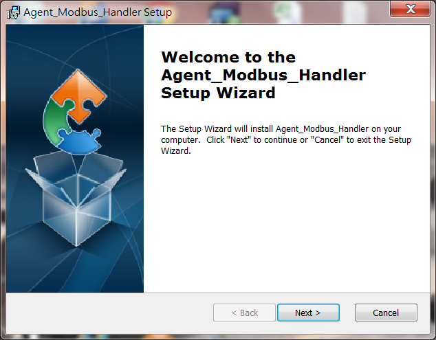
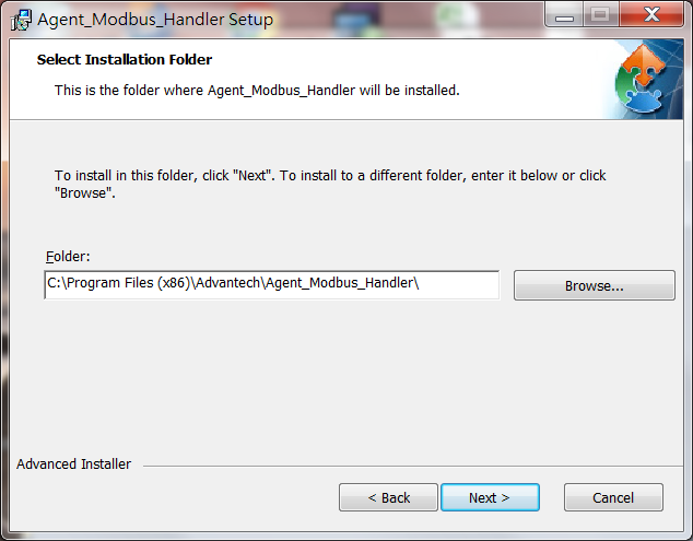
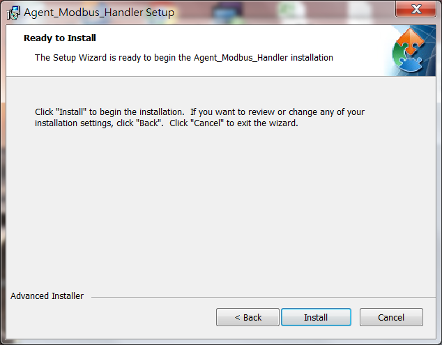
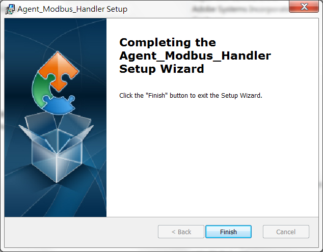
1. Double click Agent_Modbus_Handler_2.0.x.exe (Download) to start installation.
2. Click "Next" on the Welcome screen.
3. Select Installation Folder and then click "Next" to continue.
4. Click "Install" on the Ready to Install screen to continue.
5. Installation completed, click "Finish" button to exit the Setup Wizard.
Configuration
Config Modbus Connection
1. Open File Explorer and change target folder to the Modbus Service installation folder.
2. Open and edit the file Mobus_Handler.ini
2.1 Give a Name for the platform.
2.2 Set the Protocol.
Modbus TCP Connection:
Protocol=Modbus_TCP
ClientIP=(IP address of Modbus TCP devices)
ClientPort=(Port of Modbus TCP devices)
Example:
[Platform]
Name=WISE-4012E
Protocol=Modbus_TCP
ClientIP=127.0.0.1
ClientPort=502

Interval=3
#Interval: The time interval of modbus data access/report cycle in second.
Delay=0
#Delay: The time delay between two modbus address R/W in millisecond.
#Delay=0 means no delay.
Log=0

[Devices]
numberOfDevices=2
Device0=Modbus_Device0.ini
Device1=Modbus_Device1.ini
Modbus RTU Connection:
Protocol=Modbus_RTU
SlavePort=(The serial port's device node of the Gateway which connect to Modbus RTU devices)
Baud=(The baud rate for the serial port to communicate with Modbus RTU device)
Parity=(The parity of the serial port)
DataBits=(The data bits of the serial port)
StopBits=(The stop bits of the serial port)
Example:
[Platform]
Name=EKI-XXXX
Protocol=Modbus_RTU
SlavePort=COM1
Baud=19200
Parity=None
DataBits=8
StopBits=1

Interval=3
#Interval: The time interval of modbus data access/report cycle in second.
Delay=0
#Delay: The time delay between two modbus address R/W in millisecond.
#Delay=0 means no delay.
Log=0

[Devices]
numberOfDevices=2
Device0=Modbus_Device0.ini
Device1=Modbus_Device1.ini
Config Modbus Devices & Sensors
1. DeviceInfo session:
[DeviceInfo]
UnitId: The UnitID is a device ID for a Modbus TCP device.
SlaveID: The SlaveID is a device ID for a Modbus RTU device.
2. Coils session
[Coils]
NumberOfB: The number of Coils.
Bn: The sensors definitation of Coils.
3. Discrete Inputs session
[Discrete Inputs]
NumberOfIB: The number of Descrete Inputs.
IBn: The sensors definitation of Descrete Inputs.
4. Holding Registers session
[Holding Registers]
NumberOfR: The number of Holding Registers.
Rn: The sensors definitation of Holding Registers.
5. Input Registers session
[Input Registers]
NumbrtOfIR: The number of Input Registers.
IRn: The sensors definitation of Input Registers.
6. Coils Block session
NumberOfBB: The number of Coils Block.
BBn: The sensors definitation of Coils Block.
7. Discrete Input Block session
NumberOfIBB: The number of Descrete Inputs Block.
IBBn: The sensors definitation of Descrete Inputs Block.
8. Input Register Block session
NumbrtOfIRB: The number of Input Registers Block.
IRBn: The sensors definitation of Input Registers Block.
9. Holding Register session
NumberOfRB: The number of Holding Registers Block.
RBn: The sensors definitation of Holding Registers Block.
NOTE! The maximum length of sensor name is 30 characters.
Modbus_Device0.ini Example:
[DeviceInfo]
# For Modbus_TCP
UnitID=1
# For Modbus_RTU
#SlaveID=1

[Coils]
numberOfB=3
B0=0,LED0
B1=1,LED1
B2=2,LED2
Modbus_Device1.ini Example:
[DeviceInfo]
# For Modbus_TCP
UnitID=2
# For Modbus_RTU
#SlaveID=2

[Discrete Inputs]
numberOfIB=3
IB0=0,Switch0
IB1=1,Switch1
IB2=2,Switch2

[Input Registers]
numberOfIR=3
IR0=0,Data0,-1000000,1000000,1,V,0,""
IR1=1,Data1,-1000000,1000000,1,V,0,""
IR2=2,Data2,-1000000,1000000,1,V,0,""
Address and Data Types
The format and sensor address definition of sensors:
1. Single Data Format:
Tag = offset, name, min, max, precision, unit, data type, lua script
2. Block Data Format:
Block = offset, length, name
3. Tag's type, address and offset Mapping
Single Data:
| Tag | Type | Address | Offset |
| B | Coils | 00001 ~ 09999 | 0~9998 |
| IB | Descrete Inputs | 10001 ~ 19999 | 0~9998 |
| IR | Input Registers | 30001 ~ 39999 | 0~9998 |
| R | Holding Registers | 40001 ~ 49999 | 0~9998 |
Block Data:
| Block | Type | Address | Offset |
| BB | Coils Block |
00001 ~ 09999 |
0~9998 |
| IBB | Descrete Inputs Block |
10001 ~ 19999 |
0~9998 |
| IRB | Input Registers Block |
30001 ~ 39999 |
0~9998 |
| RB | Holding Registers Block |
40001 ~ 49999 |
0~9998 |
4. min and max:
The minimal and maximal range of the sensor.
5. Precision:
The value to denormalize a normalized sensor value become a floating point number.
6. Unit:
The unit for the sensor value.
7. The data type definition of sensors:
| Data Type | Description |
| 0 | 16-bit operation |
| 1 | 32-bit float no swap |
| 2 | 32-bit float byte and word swap |
| 3 | 32-bit float byte swap |
| 4 | 32-bit float word swap |
| 5 | 32-bit unsigned int no swap |
| 6 | 32-bit unsigned int word swap |
| 7 | 32-bit signed int no swap |
| 8 | 32-bit signed int word swap |
NOTE! For type of "32-bit unsigned int", the maximum support range in 0 ~ 2,147,483,647.
LUA Conversion
You can do a simple mathematic operation by add a forms in the LUA conversion string, for example:
Example1: To convert a 16-bit unsigned integer value to 16-bit signed value
[Holding Registers]
numberOfR=1
R0=0,Data0,-32768,32767,1,V,0,"(modbus_val>32767) and (modbus_val-65536) or modbus_val"
Example2: To do a mathematic forms operation.
[Holding Registers]
numberOfR=1
R0=0,Voltage0,0,5,0.001,V,0,"modbus_val*2-10"
NOTE: If both precision and LUA string are assigned, LUA string will be calculated with modbus value first, then the new value multiply with assigned precision.
LUA functions list:
https://www.kancloud.cn/thinkphp/lua-guide/43807
Docker version
To config Modbus Service and Restart Service in EdgeSense v1.0.2 Docker version:
$cd ${Installed path}/Installer/packages/Plugins/docker-edgesense-image-x86/EdgeSense/EService-Modbus/config
$sudo vim Modbus_Handler.ini
$sudo docker restart service-modbus
Real Application Case: ADAM-4117
Release
This is an overview that displays Modbus Service versions and some stats and numbers for each release.
| Index | Version | Date | Platform | OS | Release Note | Installer |
| 1 | v2.0.1 | 2018/9/6 | x86_64 CPU |
Windows |
Release Note |
Above files are available at local server, please paste file's url in File Explorer to copy file. (How to access to EOSSFS file server )


