Difference between revisions of "MCU/WISE-1510 SDK"
(modify example cmd) |
|||
| (24 intermediate revisions by 5 users not shown) | |||
| Line 86: | Line 86: | ||
*IDE: Keil uVision, DS-5, IAR Workbench. | *IDE: Keil uVision, DS-5, IAR Workbench. | ||
| − | We select GCC ARM Embedded, so you can install version 4.9 of GCC ARM Embedded ( [https://launchpad.net/gcc-arm-embedded https://launchpad.net/gcc-arm-embedded] ). | + | We select GCC ARM Embedded, so you can install version 4.9 of GCC ARM Embedded ( [[https://launchpad.net/gcc-arm-embedded/+milestone/4.9-2015-q3-update https://launchpad.net/gcc-arm-embedded/+milestone/4.9-2015-q3-update]] ). |
Note: Version 5.0 or any other versions above may be incompatible with the tools. | Note: Version 5.0 or any other versions above may be incompatible with the tools. | ||
| Line 96: | Line 96: | ||
You can get the latest stable version of mbed CLI from PyPI | You can get the latest stable version of mbed CLI from PyPI | ||
| − | <div><pre | + | <div><pre>$ pip install mbed-cli</pre> |
</div> | </div> | ||
Note: On Linux or Mac, you may need to run with sudo. | Note: On Linux or Mac, you may need to run with sudo. | ||
| Line 123: | Line 123: | ||
| | ||
| − | <div><pre>$ mbed config | + | <div><pre>$ mbed config -G GCC_ARM_PATH "C:\Program Files (x86)\GNU Tools ARM Embedded\4.9 2015q3\bin"</pre> |
| − | <pre>[mbed] C:\ | + | <pre>[mbed] C:\Program Files (x86)\GNU Tools ARM Embedded\4.9 2015q3\bin now set as global GCC_ARM_PATH</pre> |
</div> | </div> | ||
| | ||
| Line 135: | Line 135: | ||
| | ||
| − | <div><pre>$ mbed config target NUCLEO_L443RC | + | <div><pre>$ mbed config target NUCLEO_L443RC </pre> |
| − | <pre>[mbed] NUCLEO_L443RC now set as default target in program "xxxxx" | + | <pre>[mbed] NUCLEO_L443RC now set as default target in program "xxxxx" </pre> |
</div> | </div> | ||
| | ||
| − | <div><pre>$ mbed config toolchain GCC_ARM | + | <div><pre>$ mbed config toolchain GCC_ARM</pre> |
| − | <pre>[mbed] GCC_ARM now set as default toolchain in program "xxxx" | + | <pre>[mbed] GCC_ARM now set as default toolchain in program "xxxx" </pre> |
</div> | </div> | ||
| | ||
You can see the active mbed CLI configuration via: | You can see the active mbed CLI configuration via: | ||
| − | <div><pre>$ mbed config -- | + | <div><pre>$ mbed config --list</pre> |
| − | <pre>[mbed] | + | <pre>[mbed] Global config: </pre> |
| − | <pre>GCC_ARM_PATH | + | <pre>GCC_ARM_PATH=C:\Program Files (x86)\GNU Tools ARM Embedded\4.9 2015q3\bin </pre> |
| − | <pre>[mbed] Local config (xxxx): | + | <pre>[mbed] Local config (xxxx):</pre> |
| − | <pre>TOOLCHAIN=GCC_ARM | + | <pre>TOOLCHAIN=GCC_ARM</pre> |
| − | <pre>TARGET=NUCLEO_L443RC | + | <pre>TARGET=NUCLEO_L443RC</pre> |
</div> | </div> | ||
| | ||
| Line 240: | Line 240: | ||
Stack checking is turned on for all threads, and the kernel will error if an overflow condition is detected. | Stack checking is turned on for all threads, and the kernel will error if an overflow condition is detected. | ||
| − | [[File:WISE-1510-5.png]] | + | [[File:WISE-1510-5.png|RTENOTITLE]] |
=== Partitioning === | === Partitioning === | ||
| Line 246: | Line 246: | ||
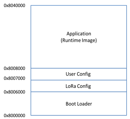
The content of flash is portioned by boot loader as below: | The content of flash is portioned by boot loader as below: | ||
| − | [[File:WISE-1510-6.png|RTENOTITLE]] | + | [[File:WISE-1510-6 new.png|RTENOTITLE]] |
Boot Loader occupies the first 16 kilo-bytes starting at 0x8000000. LoRa Config partition is used to store LoRa parameters, which occupies no more than 4 kilo-bytes. All user own parameters should be written into User Config partition, for which another 4 kilo-bytes are reserved. Application (Runtime image) partition is where users’ application is stored, up to 224 kilo-bytes can be used. | Boot Loader occupies the first 16 kilo-bytes starting at 0x8000000. LoRa Config partition is used to store LoRa parameters, which occupies no more than 4 kilo-bytes. All user own parameters should be written into User Config partition, for which another 4 kilo-bytes are reserved. Application (Runtime image) partition is where users’ application is stored, up to 224 kilo-bytes can be used. | ||
| Line 274: | Line 274: | ||
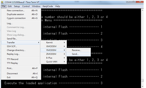
'''Step 2: Runtime image upgrade mode''' | '''Step 2: Runtime image upgrade mode''' | ||
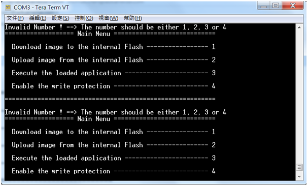
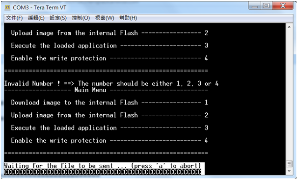
| − | Press ‘u’ on the PC keyboard and | + | Press ‘u’ on the PC keyboard and "Press reset button" on ED-20 debug board. |
The terminal will show messages as below. | The terminal will show messages as below. | ||
| Line 311: | Line 311: | ||
[[File:WISE-1510-12.png|RTENOTITLE]] | [[File:WISE-1510-12.png|RTENOTITLE]] | ||
| + | |||
| + | == Application Development == | ||
| + | |||
| + | Node APIs were provided to assist user develop applications. There are 2 UART interfaces in WISE-1510. “debug_serial” is used for user development and debug. User can see debug information of sample code via debug_serial. “m2_serial” is the UART interface of M2.com. | ||
| + | |||
| + | [[File:WISE-1510-13.png|RTENOTITLE]] | ||
| + | |||
| + | | ||
| + | |||
| + | === Node API === | ||
| + | |||
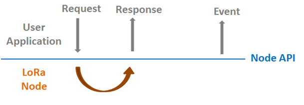
| + | <br/>Following show the architecture of the layer of LoRa Node and user application. User can send request to LoRa node via API and got response. Besides, application can also be notified by callback function if some event occurs from LoRa node. | ||
| + | |||
| + | [[File:WISE-1510-14.png|RTENOTITLE]] | ||
| + | |||
| + | The detailed description of APIs can be found in /docs/html/index.html in the released SDK. | ||
| + | |||
| + | === Sample Code for API === | ||
| + | |||
| + | If WISE-1510 was plugged in M2.com carrier board (WISE-DB1500), do below action to enable M2.com carrier board. | ||
| + | |||
| + | [[File:WISE-1510-15.png|RTENOTITLE]] | ||
| + | |||
| + | Set boud rate of debug_serial and m2_serial. | ||
| + | |||
| + | [[File:WISE-1510-16.png|RTENOTITLE]]<br/>Create sensor thread. | ||
| + | |||
| + | [[File:WISE-1510-17.png|RTENOTITLE]]<br/>Set and apply node configuration. | ||
| + | |||
| + | [[File:WISE-1510-18.png|RTENOTITLE]]<br/>Start LoRa. | ||
| + | |||
| + | [[File:WISE-1510-19.png|RTENOTITLE]]<br/>Start LoRa State loop to start rx/tx data. | ||
| + | |||
| + | [[File:WISE-1510-20.png|RTENOTITLE]] | ||
| + | |||
| + | Deep sleep mode is supported but disabled in default, please enable NODE_DEEP_SLEEP_MODE_SUPPORT if you want to try low power mode. | ||
| + | |||
| + | [[File:WISE-1510-21.png|RTENOTITLE]] | ||
| + | |||
| + | Two API were used to notify user application that LoRa finished transmit or receive action. What you should do is Register callback function in the beginning. | ||
| + | |||
| + | [[File:WISE-1510-22.png|RTENOTITLE]] | ||
| + | |||
| + | Make sure node successfully joined LoRa gateway. | ||
| + | |||
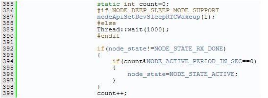
| + | [[File:WISE-1510-23.png|RTENOTITLE]]<br/>Then, start to run the state machine. If no data need to send, enter deep sleep mode and wait for waking up NODE_ACTIVE_PERIOD_IN_SEC seconds. | ||
| + | |||
| + | [[File:WISE-1510-24.png|RTENOTITLE]] | ||
| + | |||
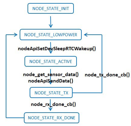
| + | This example send sensor (Temperature, Humidity) data periodically, user should modify node_get_sensor_data() to implement read sensor data. If Tx complete, node_tx_done_cb() will transfer to NODE_STATE_LOWPOWER and prepare to read/send sensor data again. If LoRa node got downlink data, node_rx_done_cb() will be invoked to get data. Then transfer to NODE_STATE_LOWPOWER. | ||
| + | |||
| + | [[File:WISE-1510-25.png|RTENOTITLE]] | ||
| + | |||
| + | The detailed description of Sample code can be found in /docs/html/index.html in the released SDK. | ||
| + | |||
| + | === Add new sensor === | ||
| + | |||
| + | This chapter is purposed to roughly describe what steps need to do for added new sensor. Currently, we take example "temperature & humidity" to explain for how to do step by step. | ||
| + | |||
| + | *Connect sensor to WISE-DB-1500 | ||
| + | |||
| + | :Please refer to [http://ess-wiki.advantech.com.tw/view/MCU/WISE-1510 WISE-1510 Pin-out Map] for which pins supported to fit M2.COM and chapter 2.4.6 & 2.4.7 in the [http://advdownload.advantech.com/productfile/Downloadfile3/1-1JR2PFY/WISE-DB1500_User_Manual_Ed.1-FINAL.pdf WISE-DB-1500 user manual]for information about CN2 and CN3 extension IO. Then, the user should review all pins-defined of CN2 & CN3 on WISE-DB-1500 and connect your sensor on it depended on what interface to access your sensor. | ||
| + | |||
| + | *Modify sample code (main.cpp) by added sensor | ||
| + | |||
| + | :After trace sample code, the user should know all things for how to add sensor. | ||
| + | |||
| + | :'''Step 1: Define macro to decide whether new sensor enabled or not"''' | ||
| + | <pre>#define NODE_SENSOR_TEMP_HUM_ENABLE 1 | ||
| + | </pre> | ||
| + | |||
| + | :'''Step 2: Add global variable to store data from sensor''' | ||
| + | <pre>#if NODE_SENSOR_TEMP_HUM_ENABLE | ||
| + | static unsigned int node_sensor_temp_hum=0; | ||
| + | #endif | ||
| + | </pre> | ||
| + | |||
| + | :'''Step 3 Create function to get data from sensor''' | ||
| + | <pre>static unsigned int hdc1510_sensor(void) | ||
| + | { | ||
| + | char data_write[3]; | ||
| + | char data_read[4]; | ||
| + | |||
| + | #define HDC1510_REG_TEMP 0x0 | ||
| + | #define HDC1510_ADDR 0x80 | ||
| + | |||
| + | data_write[0]=HDC1510_REG_TEMP; | ||
| + | i2c.write(HDC1510_ADDR, data_write, 1, 1); | ||
| + | Thread::wait(50); | ||
| + | i2c.read(HDC1510_ADDR, data_read, 4, 0); | ||
| + | float tempval = (float)((data_read[0] << 8 | data_read[1]) * 165.0 / 65536.0 - 40.0); | ||
| + | |||
| + | /*Temperature*/ | ||
| + | int ss = tempval*100; | ||
| + | unsigned int yy=0; | ||
| + | //printf("Temperature: %.2f C\r\n",tempval ); | ||
| + | /*Humidity*/ | ||
| + | float hempval = (float)((data_read[2] << 8 | data_read[3]) * 100.0 / 65536.0); | ||
| + | yy=hempval*100; | ||
| + | // printf("Humidity: %.2f %\r\n",hempval); | ||
| + | |||
| + | return (yy<<16)|ss; | ||
| + | } | ||
| + | </pre> | ||
| + | |||
| + | :Note: many peripheral APIs are supported on Mbed OS. Please refer to the below list for more details about APIs | ||
| + | :*[https://os.mbed.com/docs/v5.7/apis/serial.html Serial API] | ||
| + | :*[https://os.mbed.com/docs/v5.7/apis/i2c.html I2C API] | ||
| + | :*[https://os.mbed.com/docs/v5.7/apis/spi.html SPI API] | ||
| + | :*[https://os.mbed.com/docs/v5.7/apis/pwmout.html PWM API] | ||
| + | :*[https://os.mbed.com/docs/v5.7/apis/analogin.html ADC API] | ||
| + | :*DIO API | ||
| + | :**[https://os.mbed.com/docs/v5.7/apis/digitalin.html DigitalIn] | ||
| + | :**[https://os.mbed.com/docs/v5.7/apis/digitalout.html DigitalOut] | ||
| + | :**[https://os.mbed.com/docs/v5.7/apis/digitalinout.html DigitalInOut] | ||
| + | |||
| + | :'''Step 4 Create thread to update sensor's data periodically''' | ||
| + | <pre>In main function: | ||
| + | |||
| + | #if NODE_SENSOR_TEMP_HUM_ENABLE | ||
| + | Thread *p_node_sensor_temp_hum_thread; | ||
| + | #endif | ||
| + | ... | ||
| + | ... | ||
| + | #if NODE_SENSOR_TEMP_HUM_ENABLE | ||
| + | p_node_sensor_temp_hum_thread=new Thread(node_sensor_temp_hum_thread); | ||
| + | #endif | ||
| + | </pre> | ||
| + | <pre>In node_sensor_temp_hum_thread function: | ||
| + | |||
| + | static void node_sensor_temp_hum_thread(void const *args) | ||
| + | { | ||
| + | int cnt=0; | ||
| + | |||
| + | while(1) | ||
| + | { | ||
| + | cnt++; | ||
| + | Thread::wait(10); | ||
| + | if(cnt==100) | ||
| + | { | ||
| + | cnt=0; | ||
| + | node_sensor_temp_hum=(unsigned int )hdc1510_sensor(); | ||
| + | |||
| + | } | ||
| + | } | ||
| + | } | ||
| + | </pre> | ||
| + | |||
| + | :'''Step 5 Enclose sensor's data with TLV format''' | ||
| + | :More details about TLV format what it is, please refer to [[#Appendix_II:_Sensor_Data_Format|"Appendix II"]]. | ||
| + | <pre>In node_get_sensor_data function: | ||
| + | |||
| + | #if NODE_SENSOR_TEMP_HUM_ENABLE | ||
| + | sensor_data[len+2]=0x1; | ||
| + | len++; // temperature | ||
| + | sensor_data[len+2]=0x3; | ||
| + | len++; // len:3 bytes | ||
| + | sensor_data[len+2]=0x0; | ||
| + | len++; //0 is positive, 1 is negative | ||
| + | sensor_data[len+2]=(node_sensor_temp_hum>>8)&0xff; | ||
| + | len++; | ||
| + | sensor_data[len+2]=node_sensor_temp_hum&0xff; | ||
| + | len++; | ||
| + | sensor_data[len+2]=0x2; | ||
| + | len++; // humidity | ||
| + | sensor_data[len+2]=0x2; | ||
| + | len++; // len:2 bytes | ||
| + | sensor_data[len+2]=(node_sensor_temp_hum>>24)&0xff; | ||
| + | len++; | ||
| + | sensor_data[len+2]=(node_sensor_temp_hum>>16)&0xff; | ||
| + | len++; | ||
| + | #endif | ||
| + | </pre> | ||
| + | |||
| + | *Rebuild and flash programming | ||
| + | |||
| + | :Please refer to [[#Compilation|"Compilation"]] and [[#Flashing_Application_.28Runtime_Image.29|"Flashing Application"]] for this topic. | ||
| + | |||
| + | *Check information on console | ||
| + | |||
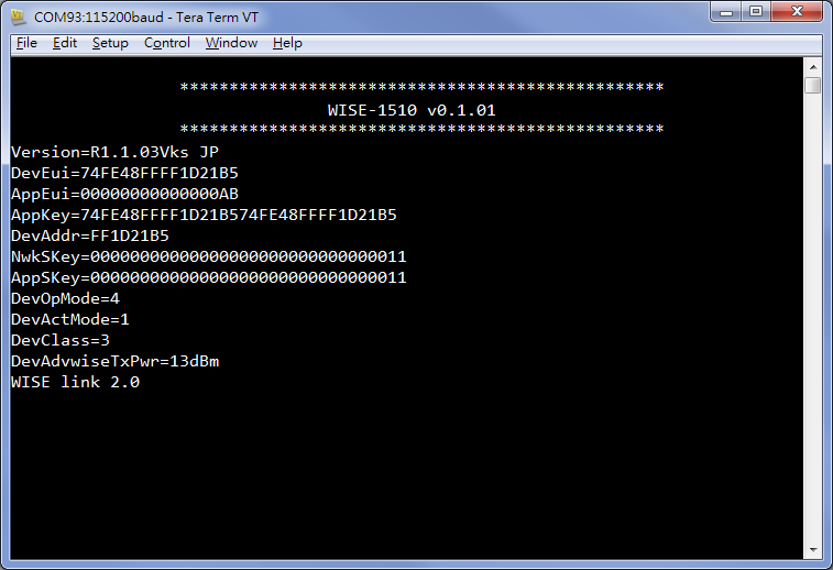
| + | :It will show you information such as DevEui,AppEui...etc. on console as below when boot up. The user will need these information for next step. | ||
| + | |||
| + | [[File:WISE-1510 bootup.png|Information on cosole]] | ||
| + | |||
| + | *Add payload field for sensor by web page on WISE-3610 | ||
| + | |||
| + | :Please refer to chapter 3.28 in the [http://advdownload.advantech.com/productfile/Downloadfile4/1-1JHTUNO/WISE-3610%20%20User%20Manual_formal_v1.0.pdf WISE-3610 user manual] for how to add payload field. | ||
| + | |||
| + | == Appendix I: Node Setup Parameters == | ||
| + | |||
| + | In the sample application, there is a function node_set_config() as below: | ||
| + | |||
| + | [[File:WISE-1510-26.png|RTENOTITLE]] | ||
| + | |||
| + | This function is used to configure all parameters of nodes. Let’s go through them briefly. | ||
| + | |||
| + | #Device EUI (DevEUI) is read from eFuse, and set without any change. | ||
| + | #Two application dependent parameters, application EUI (AppEUI) and application key (APPKey), are set respectively (line 218 and 219). | ||
| + | #Device address (DevAddr) is derived from DevEUI by extracting the last 8 bytes (line 220), and set (line 221). It’s up to users to define the format as long as it matches with gateway’s setting. | ||
| + | #Two session keys: network session key (NwkSKey) and application session key (AppSKey) are set (line 222 and 223). | ||
| + | #So far, all required parameters for node activation are set properly. Then, you can decide to activate the node by either ABP (Activation By Provisioning) or OTAA (Over-The-Air Activation). Here, we set it to ABP (line 224). Please be noted that, only three of the above parameters are used for ABP, including DevAddr, NwkSKey and AppSKey. If you’d like to use OTAA, then change the input parameter of nodeApiSetDevActMode() from 2 to 1. The other three parameters are used for OTAA, including DevEUI, AppEUI, and APPKey are set. | ||
| + | #Select nodes to work with LoRaWAN or Harmony Link by setting the device operating mode (DevOpMode): 1 for Harmony Link* and 2 for LoRaWAN. Here, Harmony Link is selected as the default. (line 225) If you’d like to use LoRaWAN, change it from 1 to 2. | ||
| + | |||
| + | *Harmony Link is Advantech’s proprietary LoRa MAC. | ||
| + | |||
| + | #You can select which class of Node: 1 for Class A, and 3 for Class C. (2 for Class B is reserved for future use.) Here, Class C is selected (line 226). | ||
| + | #The remaining part are used to set radio related parameters, including data rate (DevAdvwiseDataRate), frequency (DevAdvwiseFreq) and transmission power (DevAdvwiseTxPwr) (line 227~229). Please be noted all of RF parameters are region dependent, so you’ve to set their values accordingly. Make sure you DO NOT violate the regional regulation. | ||
| + | |||
| + | After all parameters are configured, be reminded to apply them by nodeApiApplyCfg(). | ||
| + | |||
| + | == Appendix II: Sensor Data Format == | ||
| + | |||
| + | In the sample application, node_get_sensor_data() encodes sensor data according to the following format: | ||
| + | |||
| + | [[File:WISE-1510-27.png|RTENOTITLE]] | ||
| + | |||
| + | ,where | ||
| + | |||
| + | Length: Total TLV length | ||
| + | |||
| + | MsgType: Fixed as 0xc | ||
| + | |||
| + | Multiple TLVs are one or more Tag-Length-Values: tag matches with gateway’s setting, length is sensor data length, and value is sensor data. All octets are in hexadecimal. | ||
| + | |||
| + | For example, LoRa Payload Field setting on WISE-3610 is as below: | ||
| + | |||
| + | [[File:1510payload.JPG|800px|1510payload.JPG]] | ||
| + | |||
| + | If temperature is 25.55 Celsius degree, translate decimal 2555 to hexadecimal 9FB. Similarly, if humidity is 60.55%, translate from decimal 6055 to hexadecimal 17A7. The encoded data will be | ||
| + | |||
| + | 0x9 | 0xc | 0x1 | 0x3 | 0x0 | 0x9 | 0xFB | 0x2 | 0x2 | 0x17 | 0xA7 | ||
| + | |||
| + | , where | ||
| + | |||
| + | 0x9: the Total TLV length, included two TLVs | ||
| + | |||
| + | 0xc: the fixed MsgType | ||
| + | |||
| + | 0x1 | 0x3 | 0x0 | 0x9 | 0xFB: the first TLV with tag id (0x1), value length (0x3), and positive (0x0)、 negative(0xff), value (0x9FB) | ||
| + | |||
| + | 0x2 | 0x2 | 0x17 | 0xA7: the second TLV with tag id (0x2), value length (0x2), and unsigned value (0x17A7) | ||
| + | |||
| + | Be reminded temperature “Sign” setting is On, 1 extra byte is required to indicate (0 means positive, and 0xFF means negative) , but humidity "Sign" setting on gateway is Off, so no extra 1 byte is required. | ||
| + | |||
| + | Users are free to define their own payload field format, but only sensor data encoded according to the above format can be decoded successfully, and displayed on LoRa Dashboard on WISE-3610. | ||
| + | |||
| + | == Appendix III: Application Sample Code Flow == | ||
| + | |||
| + | [[File:Application Sample Code Flow.png|RTENOTITLE]] | ||
| + | |||
| + | == Appendix IV: Windows Node CLI Client [[Media:Windows_node_cli_client.zip|[download]]] == | ||
| + | |||
| + | == Appendix V: Docker install and setting == | ||
| + | |||
| + | <span style="font-size:larger">'''<span style="color:#0070c0">If you don't have docker in your system, then you can follow the below steps to install docker and run it first.</span>'''</span> | ||
| + | |||
| + | === <span style="color:#0070c0">To install Docker Engine on your platform</span> === | ||
| + | |||
| + | :Please refer to [https://docs.docker.com/engine/installation/ Docker Installation Guide] for details | ||
| + | |||
| + | === <span style="color:#0070c0">To pull [https://hub.docker.com/r/advantechwiseec/mbed mbed image from Docker Hub] </span> === | ||
| + | |||
| + | :<code>$ docker pull advantechwiseec/mbed</code><br/> | ||
| + | |||
| + | === <span style="color:#0070c0">To create container</span> === | ||
| + | |||
| + | :<code>$ docker run -v '''${Local_share_path}''':'''${Container_folder_path}''' -it '''${Docker_Image_ID}''' /bin/bash</code><br/> | ||
| + | <pre>ex: | ||
| + | $ mkdir C:\tmp | ||
| + | $ docker run -v /c/tmp:/opt/share -it aae6dcebc659 /bin/bash</pre> | ||
| + | |||
| + | === <span style="color:#0070c0">To clone WISE-1510 SDK</span> === | ||
| + | |||
| + | :<code>$ mkdir -p /m2com;cd /m2com</code><br/> | ||
| + | :<code>$ git clone [https://github.com/ADVANTECH-Corp/WISE-1510.git https://github.com/ADVANTECH-Corp/WISE-1510.git]</code><br/> | ||
| + | |||
| + | === <span style="color:#0070c0">To build WISE-1510 SDK</span> === | ||
| + | |||
| + | :<code>$ cd /m2com/WISE-1510</code><br/> | ||
| + | :<code>$ ./make.sh</code><br/> | ||
| + | :<code>$ cp BUILD/MTB_ADV_WISE_1510/GCC_ARM/WISE-1510.bin /opt/share/</code><br/> | ||
| + | :You can get WISE-1510.bin in '''${Local_share_path}''' | ||
Latest revision as of 03:29, 22 May 2020
Contents
- 1 Introduction
- 2 Quick Starter of WISE-1510
- 3 Development Environment Setup
- 4 Application Development
- 5 Appendix I: Node Setup Parameters
- 6 Appendix II: Sensor Data Format
- 7 Appendix III: Application Sample Code Flow
- 8 Appendix IV: Windows Node CLI Client [download]
- 9 Appendix V: Docker install and setting
Introduction
WISE-1510 is a wireless module integrated with ARM Cortex-M4 Processor and LoRa / LoRaWAN connectivity. This technology is the best solution for Low-Power Wide-Area Network (LPWAN) Applications. LoRaWAN is defined to optimize the power consumption and wide range. Your sensors or applications with low data rate requirement can be achieved years battery lifetime and kilometers long distance connection. Advantech WISE-1510 also provides multi-interfaces for sensor and I/O control. With ARM mbed embedded microprocessor operating system and add-on software stacks, it's convenient to build the application software or sensor algorithm over mbed OS. Data can be quickly and easily acquired and transformed into a different format to communicate with WISE-PaaS or other cloud services. Developer can build their application backbone faster and focus on their applications, value-added services.
Quick Starter of WISE-1510
Debug Port Connection
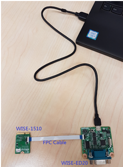
- Connect debug port FPC cable to WISE-1510 debug port (CN1; on the back of PCB)
- Connect WISE-ED20 debug board to the FPC debug cable.
- Connect USB-to-microUSB cable from WISE-ED20 to the USB port on your PC.
Debug Port Setting
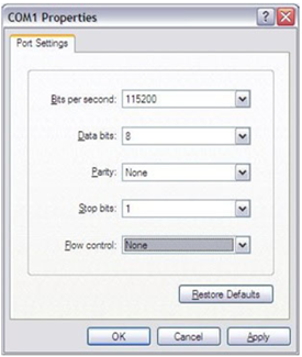
WISE-1510 can communicate with a host server (Windows or Linux) by using serial cables. Common serial communication programs such as Hyper Terminal, Tera Term or PuTTY can be used in this case. The example below describes the serial terminal setup using Hyper Terminal on a Windows host:
- Connect WISE-ED20 with your Windows PC by using a serial cable.
- Open Hyper Terminal on your Windows PC, and select the settings as shown below.
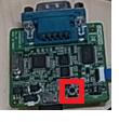
- Press reset (red-frame) button on ED-20.
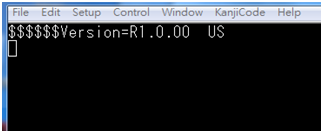
- Terminal will show the image version
Development Environment Setup
Overview
ARM mbed is used for you to create applications running on WISE-1510. Your application code is written in C++. It uses the application programming interfaces (APIs) that mbed OS provides. These APIs allow your code to work on different microcontrollers in a uniform way. This reduces a lot of the challenges in getting started with microcontrollers and integrating large amounts of software. Besides, we also provide you node APIs which facilitates LoRa node development. Our offline development tool is the mbed CLI, a command-line tool. This requires having a toolchain installed on your computer. mbed CLI is the name of the ARM mbed command-line tool, packaged as mbed-cli, which enables the full mbed workflow: repositories version control, maintaining dependencies, publishing code, updating from remotely hosted repositories and invoking ARM mbed’s own build system and export functions, among other operations. The basic workflow for mbed CLI is to:
- Initialize a new repository, for either a new application (or library) or an imported one.
- Build the application code.
- Test your build.
- Publish your application.
Installation
To install mbed CLI, related tools are required to be installed first. Please refer to the video tutorial. ( https://www.youtube.com/watch?v=cM0dFoTuU14 )
Please follow the steps described in the tutorial video to install mbed CLI.
- Install Python
mbed CLI supports Windows, Linux and Mac OS X operating systems. You can select the OS you prefer to work with. mbed CLI is a Python script, so you’ll need Python to use it. The version 2.7.11 of Python has been verified with mbed CLI.
https://www.python.org/downloads/release/python-2711/
Note: mbed CLI is incompatible with Python 3.
- (Optional) Install Git or Mercurial
If you would like to maintain your source code in repositories, you can continue with the next step. mbed CLI supports both Git and Mercurial repositories, you can install which one you prefer:
Git - version 1.9.5 or later ( https://git-scm.com/ ).
Mercurial - version 2.2.2 or later ( https://www.mercurial-scm.org/ ).
If you don’t want to use repositories, you can just skip it.
- Install gcc
mbed CLI invokes the mbed OS 5 tools for various features, such as compiling, testing and exporting to industry standard toolchains. To compile your code, you will need either a compiler or an IDE:
- Compilers: GCC ARM, ARM Compiler 5, IAR.
- IDE: Keil uVision, DS-5, IAR Workbench.
We select GCC ARM Embedded, so you can install version 4.9 of GCC ARM Embedded ( [https://launchpad.net/gcc-arm-embedded/+milestone/4.9-2015-q3-update] ).
Note: Version 5.0 or any other versions above may be incompatible with the tools.
- Install mbed CLI
You can get the latest stable version of mbed CLI from PyPI
$ pip install mbed-cli
Note: On Linux or Mac, you may need to run with sudo.
Finally, you’ve to extract the source code to the working directory from the SDK we released. The structure of the working directory is as below:
docs/ <-- Documents for SDK
loranode_L443_sdk_R1_0_02/mbed-os/ <-- mbed os
loranode_L443_sdk_R1_0_02/libHLLoraNode.a <-- Harmony Link Lora Node library
loranode_L443_sdk_R1_0_02/node_api.h <-- Node API header file
loranode_L443_sdk_R1_0_02/main.cpp <-- Sample code
Configuration
After the installation of required tool chains, please set up the directory of mbed CLI to link the folder of toolchains which you want to use for compiling the source tree.
You can set the GCC ARM Embedded location via the command as below:
$ mbed config -G GCC_ARM_PATH "C:\Program Files (x86)\GNU Tools ARM Embedded\4.9 2015q3\bin"
[mbed] C:\Program Files (x86)\GNU Tools ARM Embedded\4.9 2015q3\bin now set as global GCC_ARM_PATH
Next, you can select the tool chain and target platform which mbed CLI uses to build applications. Change directory to target mbed program.
$ mbed config target NUCLEO_L443RC
[mbed] NUCLEO_L443RC now set as default target in program "xxxxx"
$ mbed config toolchain GCC_ARM
[mbed] GCC_ARM now set as default toolchain in program "xxxx"
You can see the active mbed CLI configuration via:
$ mbed config --list
[mbed] Global config:
GCC_ARM_PATH=C:\Program Files (x86)\GNU Tools ARM Embedded\4.9 2015q3\bin
[mbed] Local config (xxxx):
TOOLCHAIN=GCC_ARM
TARGET=NUCLEO_L443RC
Compilation
mbed CLI uses the current directory as a working context. This means that before calling any mbed CLI command, you must first change to the working directory containing the code. Then, Use the mbed compile command to compile your code:
$ mbed compile -c
Building project xxxxx (NUCLEO_L443RC, GCC_ARM)
Scan: .
Scan: mbed
Scan: env
Compile [ 0.5%]: base64.cpp
Compile [ 1.0%]: oslmic.cpp
…
Compile [100.0%]: node_sapi.cpp
Link: xxxxx
Elf2Bin: xxxxx
+--------------------+--------+-------+-------+
| Module | .text | .data | .bss |
+--------------------+--------+-------+-------+
| Fill | 223 | 16 | 41 |
| Misc | 104316 | 7804 | 5017 |
| drivers | 3592 | 4 | 224 |
| hal | 802 | 0 | 8 |
| platform | 1782 | 4 | 297 |
| rtos | 910 | 4 | 4 |
| rtos/rtx | 7369 | 20 | 6870 |
| targets/TARGET_STM | 19944 | 4 | 1719 |
| Subtotals | 138938 | 7856 | 14180 |
+--------------------+--------+-------+-------+
Allocated Heap: unknown
Allocated Stack: unknown
Total Static RAM memory (data + bss): 22036 bytes
Total RAM memory (data + bss + heap + stack): 22036 bytes
Total Flash memory (text + data + misc): 146794 bytes
Image: ./BUILD/NUCLEO_L443RC/GCC_ARM/xxxxx.bin
Now, you have your application in binary format ready for flashing.
Memory Layout
A basic overview of mbed memory model is as below:
Each thread of execution in the RTOS has a separate stack. When you use the RTOS, before explicitly initializing any additional thread, you will have four separate stacks:
• The stack of the main thread (executing the main function).
• The idle thread executed each time all the other threads are waiting for external or scheduled events. This is particularly useful for implementing energy saving strategies (like sleep).
• The timer thread that executes all the time-scheduled tasks (periodic and nonperiodic).
• The stack of OS scheduler itself (also used by the ISRs).
Stack checking is turned on for all threads, and the kernel will error if an overflow condition is detected.
Partitioning
The content of flash is portioned by boot loader as below:
Boot Loader occupies the first 16 kilo-bytes starting at 0x8000000. LoRa Config partition is used to store LoRa parameters, which occupies no more than 4 kilo-bytes. All user own parameters should be written into User Config partition, for which another 4 kilo-bytes are reserved. Application (Runtime image) partition is where users’ application is stored, up to 224 kilo-bytes can be used.
Flashing Application (Runtime Image)
To flash runtime image, your terminal program needs to support “Y-Modem”.
Tera Term is used for demonstration here.
Step 1. UART port connect via debug board
Connect USB-to-microUSB cable from WISE-ED20 to the USB port on your Windows PC.
Open the corresponding COM port in serial program, ex: Tera Term.
Set baud rate to 115200.
Step 2: Runtime image upgrade mode
Press ‘u’ on the PC keyboard and "Press reset button" on ED-20 debug board.
The terminal will show messages as below.
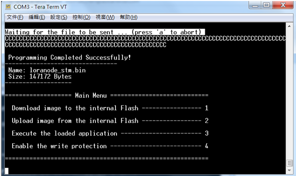
Press "1" to “Download image to the internal Flash”.
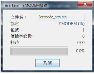
Step 3: Start upgrading via Y modem
Select the run-time image ".bin" file via Y-Modem.
Waiting for run-time image transmission is complete.
After downloading completed, the terminal will show as below.
Step 4: Reset device
Press reset button on ED-20 debug board to reset device.
Testing
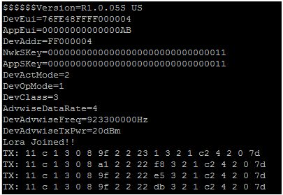
Now, you’re ready to test your WISE-1510. The sample application we created is to send sensor data every 5 seconds via LoRa if values are changed. To observe it, you can connect the debug port as described earlier. After reset WISE-1510, the result is shown on your Terminal as below:
Application Development
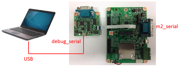
Node APIs were provided to assist user develop applications. There are 2 UART interfaces in WISE-1510. “debug_serial” is used for user development and debug. User can see debug information of sample code via debug_serial. “m2_serial” is the UART interface of M2.com.
Node API
Following show the architecture of the layer of LoRa Node and user application. User can send request to LoRa node via API and got response. Besides, application can also be notified by callback function if some event occurs from LoRa node.
The detailed description of APIs can be found in /docs/html/index.html in the released SDK.
Sample Code for API
If WISE-1510 was plugged in M2.com carrier board (WISE-DB1500), do below action to enable M2.com carrier board.
Set boud rate of debug_serial and m2_serial.
![]()
Set and apply node configuration.

Start LoRa State loop to start rx/tx data.
Deep sleep mode is supported but disabled in default, please enable NODE_DEEP_SLEEP_MODE_SUPPORT if you want to try low power mode.
Two API were used to notify user application that LoRa finished transmit or receive action. What you should do is Register callback function in the beginning.
Make sure node successfully joined LoRa gateway.

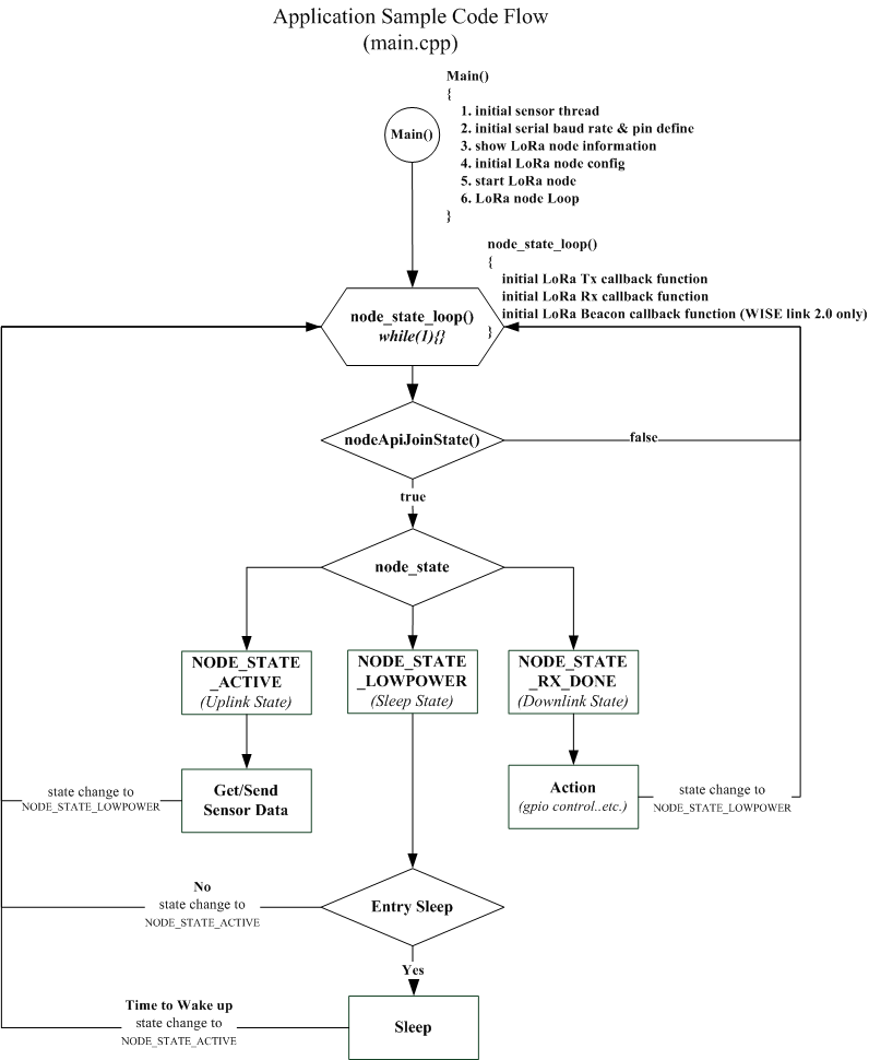
Then, start to run the state machine. If no data need to send, enter deep sleep mode and wait for waking up NODE_ACTIVE_PERIOD_IN_SEC seconds.
This example send sensor (Temperature, Humidity) data periodically, user should modify node_get_sensor_data() to implement read sensor data. If Tx complete, node_tx_done_cb() will transfer to NODE_STATE_LOWPOWER and prepare to read/send sensor data again. If LoRa node got downlink data, node_rx_done_cb() will be invoked to get data. Then transfer to NODE_STATE_LOWPOWER.
The detailed description of Sample code can be found in /docs/html/index.html in the released SDK.
Add new sensor
This chapter is purposed to roughly describe what steps need to do for added new sensor. Currently, we take example "temperature & humidity" to explain for how to do step by step.
- Connect sensor to WISE-DB-1500
- Please refer to WISE-1510 Pin-out Map for which pins supported to fit M2.COM and chapter 2.4.6 & 2.4.7 in the WISE-DB-1500 user manualfor information about CN2 and CN3 extension IO. Then, the user should review all pins-defined of CN2 & CN3 on WISE-DB-1500 and connect your sensor on it depended on what interface to access your sensor.
- Modify sample code (main.cpp) by added sensor
- After trace sample code, the user should know all things for how to add sensor.
- Step 1: Define macro to decide whether new sensor enabled or not"
#define NODE_SENSOR_TEMP_HUM_ENABLE 1
- Step 2: Add global variable to store data from sensor
#if NODE_SENSOR_TEMP_HUM_ENABLE
static unsigned int  node_sensor_temp_hum=0;
#endif
- Step 3 Create function to get data from sensor
static unsigned int hdc1510_sensor(void)
{
	char data_write[3];
	char data_read[4];

	#define HDC1510_REG_TEMP  0x0
	#define HDC1510_ADDR 0x80

	data_write[0]=HDC1510_REG_TEMP;
	i2c.write(HDC1510_ADDR, data_write, 1, 1);
	Thread::wait(50);
	i2c.read(HDC1510_ADDR, data_read, 4, 0);
	float tempval = (float)((data_read[0] << 8 | data_read[1]) * 165.0 / 65536.0 - 40.0);

	/*Temperature*/
	int ss = tempval*100;
	unsigned int yy=0;
	//printf("Temperature: %.2f C\r\n",tempval );
	/*Humidity*/
	float hempval = (float)((data_read[2] << 8 | data_read[3]) * 100.0 / 65536.0);
	yy=hempval*100;
	// printf("Humidity: %.2f %\r\n",hempval);

	return (yy<<16)|ss;
}
- Note: many peripheral APIs are supported on Mbed OS. Please refer to the below list for more details about APIs
- Step 4 Create thread to update sensor's data periodically
In main function:

#if NODE_SENSOR_TEMP_HUM_ENABLE
	Thread *p_node_sensor_temp_hum_thread;
#endif
...
...
#if NODE_SENSOR_TEMP_HUM_ENABLE
	p_node_sensor_temp_hum_thread=new Thread(node_sensor_temp_hum_thread);
#endif
In node_sensor_temp_hum_thread function:

static void node_sensor_temp_hum_thread(void const *args)
{
    	int cnt=0;

    	while(1)
	{
	    cnt++;
	    Thread::wait(10);
	    if(cnt==100)
	    {
	       cnt=0;
	     	node_sensor_temp_hum=(unsigned int )hdc1510_sensor();

	     }
	}
}
- Step 5 Enclose sensor's data with TLV format
- More details about TLV format what it is, please refer to "Appendix II".
In node_get_sensor_data function:

#if NODE_SENSOR_TEMP_HUM_ENABLE
	sensor_data[len+2]=0x1;
	len++; // temperature
	sensor_data[len+2]=0x3;
	len++;  // len:3 bytes
	sensor_data[len+2]=0x0;
	len++; //0 is positive, 1 is negative
	sensor_data[len+2]=(node_sensor_temp_hum>>8)&0xff;
	len++;
	sensor_data[len+2]=node_sensor_temp_hum&0xff;
	len++;
	sensor_data[len+2]=0x2;
	len++;  // humidity
	sensor_data[len+2]=0x2;
	len++; // len:2 bytes
	sensor_data[len+2]=(node_sensor_temp_hum>>24)&0xff;
	len++;
	sensor_data[len+2]=(node_sensor_temp_hum>>16)&0xff;
	len++;
#endif
- Rebuild and flash programming
- Please refer to "Compilation" and "Flashing Application" for this topic.
- Check information on console
- It will show you information such as DevEui,AppEui...etc. on console as below when boot up. The user will need these information for next step.
- Add payload field for sensor by web page on WISE-3610
- Please refer to chapter 3.28 in the WISE-3610 user manual for how to add payload field.
Appendix I: Node Setup Parameters
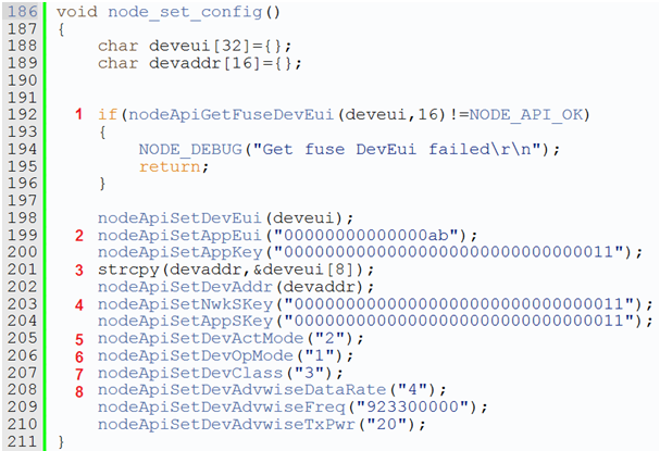
In the sample application, there is a function node_set_config() as below:
This function is used to configure all parameters of nodes. Let’s go through them briefly.
- Device EUI (DevEUI) is read from eFuse, and set without any change.
- Two application dependent parameters, application EUI (AppEUI) and application key (APPKey), are set respectively (line 218 and 219).
- Device address (DevAddr) is derived from DevEUI by extracting the last 8 bytes (line 220), and set (line 221). It’s up to users to define the format as long as it matches with gateway’s setting.
- Two session keys: network session key (NwkSKey) and application session key (AppSKey) are set (line 222 and 223).
- So far, all required parameters for node activation are set properly. Then, you can decide to activate the node by either ABP (Activation By Provisioning) or OTAA (Over-The-Air Activation). Here, we set it to ABP (line 224). Please be noted that, only three of the above parameters are used for ABP, including DevAddr, NwkSKey and AppSKey. If you’d like to use OTAA, then change the input parameter of nodeApiSetDevActMode() from 2 to 1. The other three parameters are used for OTAA, including DevEUI, AppEUI, and APPKey are set.
- Select nodes to work with LoRaWAN or Harmony Link by setting the device operating mode (DevOpMode): 1 for Harmony Link* and 2 for LoRaWAN. Here, Harmony Link is selected as the default. (line 225) If you’d like to use LoRaWAN, change it from 1 to 2.
- Harmony Link is Advantech’s proprietary LoRa MAC.
- You can select which class of Node: 1 for Class A, and 3 for Class C. (2 for Class B is reserved for future use.) Here, Class C is selected (line 226).
- The remaining part are used to set radio related parameters, including data rate (DevAdvwiseDataRate), frequency (DevAdvwiseFreq) and transmission power (DevAdvwiseTxPwr) (line 227~229). Please be noted all of RF parameters are region dependent, so you’ve to set their values accordingly. Make sure you DO NOT violate the regional regulation.
After all parameters are configured, be reminded to apply them by nodeApiApplyCfg().
Appendix II: Sensor Data Format
In the sample application, node_get_sensor_data() encodes sensor data according to the following format:
,where
Length: Total TLV length
MsgType: Fixed as 0xc
Multiple TLVs are one or more Tag-Length-Values: tag matches with gateway’s setting, length is sensor data length, and value is sensor data. All octets are in hexadecimal.
For example, LoRa Payload Field setting on WISE-3610 is as below:
If temperature is 25.55 Celsius degree, translate decimal 2555 to hexadecimal 9FB. Similarly, if humidity is 60.55%, translate from decimal 6055 to hexadecimal 17A7. The encoded data will be
0x9 | 0xc | 0x1 | 0x3 | 0x0 | 0x9 | 0xFB | 0x2 | 0x2 | 0x17 | 0xA7
, where
0x9: the Total TLV length, included two TLVs
0xc: the fixed MsgType
0x1 | 0x3 | 0x0 | 0x9 | 0xFB: the first TLV with tag id (0x1), value length (0x3), and positive (0x0)、 negative(0xff), value (0x9FB)
0x2 | 0x2 | 0x17 | 0xA7: the second TLV with tag id (0x2), value length (0x2), and unsigned value (0x17A7)
Be reminded temperature “Sign” setting is On, 1 extra byte is required to indicate (0 means positive, and 0xFF means negative) , but humidity "Sign" setting on gateway is Off, so no extra 1 byte is required.
Users are free to define their own payload field format, but only sensor data encoded according to the above format can be decoded successfully, and displayed on LoRa Dashboard on WISE-3610.
Appendix III: Application Sample Code Flow
Appendix IV: Windows Node CLI Client [download]
Appendix V: Docker install and setting
If you don't have docker in your system, then you can follow the below steps to install docker and run it first.
To install Docker Engine on your platform
- Please refer to Docker Installation Guide for details
To pull mbed image from Docker Hub
$ docker pull advantechwiseec/mbed
To create container
$ docker run -v ${Local_share_path}:${Container_folder_path} -it ${Docker_Image_ID} /bin/bash
ex:
$ mkdir C:\tmp
$ docker run -v /c/tmp:/opt/share -it aae6dcebc659 /bin/bash
To clone WISE-1510 SDK
$ mkdir -p /m2com;cd /m2com$ git clone https://github.com/ADVANTECH-Corp/WISE-1510.git
To build WISE-1510 SDK
$ cd /m2com/WISE-1510$ ./make.sh$ cp BUILD/MTB_ADV_WISE_1510/GCC_ARM/WISE-1510.bin /opt/share/- You can get WISE-1510.bin in ${Local_share_path}
