|
|
| (37 intermediate revisions by the same user not shown) |
| Line 1: |
Line 1: |
| | + | |
| | = Introduction = | | = Introduction = |
| | | | |
| Line 7: |
Line 8: |
| | <span style="font-size:medium;">Modbus Service is a Windows/Linux system service for WISE Agent to read sensor data from Modbus device or write data into Modbus device. After sensor data are acquired, WISE Agent will upload the data to the WISE-PaaS Cloud.</span> | | <span style="font-size:medium;">Modbus Service is a Windows/Linux system service for WISE Agent to read sensor data from Modbus device or write data into Modbus device. After sensor data are acquired, WISE Agent will upload the data to the WISE-PaaS Cloud.</span> |
| | | | |
| | + | |
| | | | |
| | + | |
| | | | |
| | = Features = | | = Features = |
| Line 15: |
Line 18: |
| | <span style="font-size:medium;">Feature:</span> | | <span style="font-size:medium;">Feature:</span> |
| | | | |
| − | *<span style="font-size:medium;">Support connection with multiple Modbus slave.</span> | + | *<span style="font-size:medium;">Support connection with multiple Modbus slave.</span> |
| − | *<span style="font-size:medium;">Support access both Modbus TCP and RTU in one service.</span> | + | *<span style="font-size:medium;">Support access both Modbus TCP and RTU in one service.</span> |
| − | *<span style="font-size:medium;">Support individual read interval by connection.</span> | + | *<span style="font-size:medium;">Support individual read interval by connection.</span> |
| − | *<span style="font-size:medium;">Configurable sensor alias.</span> | + | *<span style="font-size:medium;">Configurable sensor alias.</span> |
| − | *<font size="3">Support byte swap.</font> | + | *<font size="3">Support byte swap.</font> |
| − | *<span style="font-size:medium;">Currently support up-link Modbus Coil, Descrete input, Input register & Holding register data to WISE-PaaS , not support down-link from WISE-PaaS.</span> | + | *<span style="font-size:medium;">Support Modbus Coil, Descrete input, Input register & Holding register data.</span> |
| − | *<font size="3">Support maximal 10 links, 10 devices for each link, and 30 sensors for each device.</font> | + | *<font size="3">Support maximal 10 links, 5 devices for each link, and 10 sensors for each device.</font> |
| | | | |
| | = How to = | | = How to = |
| | | | |
| − | == Software Requirements == | + | == Login == |
| − | | |
| − | *<span style="font-size:medium;">MQTT broker ([https://www.dropbox.com/s/cijybdsex900737/MQTTBrokerSetup_1.0.4.exe?dl=0 download link])</span>
| |
| − | *<span style="font-size:medium;">WISE Agent and enabled its connection with DeviceOn server </span>
| |
| − | | |
| − | == Installation ==
| |
| | | | |
| − | <span style="font-size:medium;">'''Windows:'''</span>
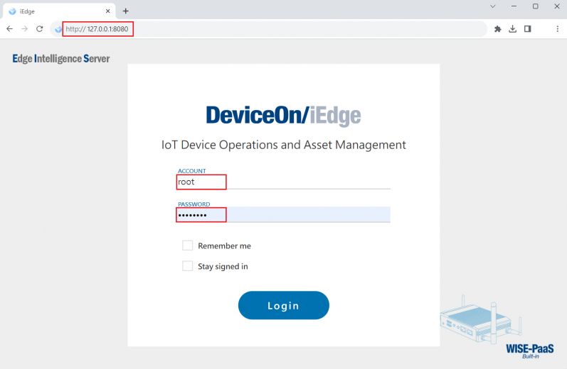
| + | Step 1. Launch a web browser (Google Chrome, Microsoft Edge ...) and open iEdge local web '''[http://127.0.0.1:8080 http://127.0.0.1:8080]''' |
| | | | |
| − | <span style="font-size:medium;">1. Download Modbus-Master for Windows from [http://ess-wiki.advantech.com.tw/view/Modbus-Master#Release Release] Table.</span>
| + | Step 2. Login iEdge local web: |
| | | | |
| − | <span style="font-size:medium;">2. Double click the installer to launch the installer to install it to the machine.</span>
| + | Account: '''root''' |
| | | | |
| − | <span style="font-size:medium;">'''Debian:'''</span>
| + | Password: '''P@ssw0rd''' |
| | | | |
| − | <span style="font-size:medium;">1. Download Modbus-Master for Debian from [http://ess-wiki.advantech.com.tw/view/Modbus_Master#Release Release] Table.</span>
| + | [[File:Ros2-iedge-plugin-config-01.png|frameless|900x520px|Ros2-iedge-plugin-config-01.png]] |
| | | | |
| − | <span style="font-size:medium;">2. Launch the installer to install it to the machine.</span>
| + | |
| − | <pre>sudo ./device-modbus-master-3.0.1-Debian_9.9-rk3399.run
| |
| − | </pre>
| |
| | | | |
| | == Configuration == | | == Configuration == |
| | | | |
| − | <span style="font-size:medium;">EdgeSense Modbus Master can manage multiple Modbus Slave setting and individual sensor's parameters, below settings are default after Modbus Master installation.</span>
| + | === How to config Model === |
| − | | |
| − | | |
| | | | |
| − | <span style="font-size:medium;">1. Device Configuration: <Install_folder>\config\industry\device-industry.yaml</span>
| + | Step 1. Go to "Plug-ins" / Plugin Config to select Modbus-Master Plug-in |
| − | <pre>metadata:
| |
| − | name: "Modbus devices"
| |
| − | labels: ["Modbus"]
| |
| − | Description: "Modbus TCP/RTU devices with 3 sensors in holding register area 40001~40003"
| |
| − | UpdateData: 2020-01-08-14:25:30
| |
| | | | |
| − | # LinkInfo: You can add a new link with unique name
| + | [[File:Modbus config bQUoHri.png|border|800x480px|Modbus config bQUoHri.png]] |
| − | # <LinkName>: Unique Link Name
| |
| − | # Params: Serial Port or Network parameters
| |
| − | # Info: Time interval of polling data & check link
| |
| − | # DevList: Device list which defined in DeviceInfo section
| |
| | | | |
| − | LinkInfo:
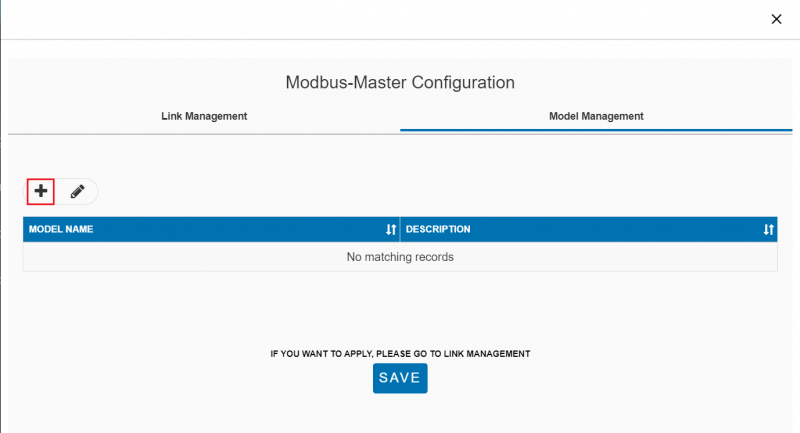
| + | Setp 2. From Modbus-Master Configuration, open Model Management tab, click "+" to add new Model. |
| − | TCP-IP-1:
| |
| − | Params:
| |
| − | Driver: Modbus-TCP
| |
| − | ConnectType: Net
| |
| − | IP: 127.0.0.1
| |
| − | Port: 502
| |
| − | Timeout: 1000 # A request timeout in milliseconds
| |
| − |
| |
| − | Info:
| |
| − | PollingInterval: 3000 # Polling interval in milliseconds
| |
| − | Retry: 3 # Count of retry min:0 max:3
| |
| − | AliveTime: 10 # Link Timeout in second: SDK will release this link if there are any request over this AliveTime ( second )
| |
| − | CheckLinkInterval: 2 # Check link status interval (second)
| |
| | | | |
| − | DevList:
| + | [[File:Modbus config qpMUDCj.png|border|800x480px|modbus_config_qpMUDCj.png]] |
| − | - Device-1
| |
| | | | |
| − | COM1:
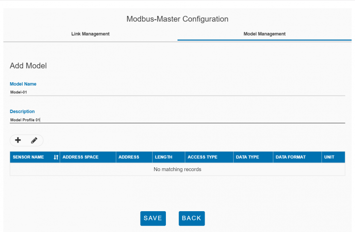
| + | Setp 3. Input Model name and Description for new Model. |
| − | Params:
| |
| − | Driver: Modbus-RTU
| |
| − | ConnectType: Serial
| |
| − | PortName: COM1
| |
| − | BaudRate: 9600
| |
| − | DataBits: 8
| |
| − | StopBits: 1
| |
| − | Parity: None
| |
| − | Timeout: 1000 # A request timeout in milliseconds
| |
| − |
| |
| − | Info:
| |
| − | PollingInterval: 3000 # Polling interval in milliseconds
| |
| − | Retry: 3 # Count of retry min:0 max:3
| |
| − | AliveTime: 10 # Link Timeout in second: SDK will release this link if there are any request over this AliveTime ( second )
| |
| − | CheckLinkInterval: 2 # Check link status interval (second)
| |
| | | | |
| − | DevList:
| + | [[File:Modbus config XLSJYyn.png|border|800x480px|modbus_config_XLSJYyn.png]] |
| − | - Device-2
| |
| | | | |
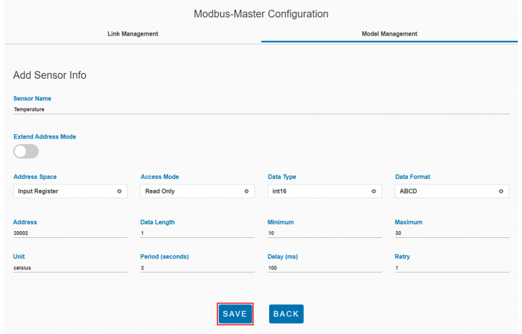
| | + | Step 4. Click "+" to add Sensor - Input Sensor Name - Select Address Space, Access mode, Data Type, Data Format and input Address, Data Length, Minimal/Maximal Value for new sensor's attributes. - Input below timing attributes: Period (second) . Delay (ms, range: 0~1000ms) and Retry (range: 0~5) |
| | | | |
| − | # DeviceInfo: You can add a new device with unique name
| + | *Click "Save" button to save the new sensor. |
| − | # <DeviceName>: Unique Device Name
| |
| − | # Params: Station number
| |
| − | # Profile: Profile file name
| |
| | | | |
| − | DeviceInfo:
| + | [[File:Modbus config qsox6hM.png|border|800x480px|modbus_config_qsox6hM.png]] |
| − | Device-1:
| |
| − | Params:
| |
| − | Station: 1
| |
| | | | |
| − | Profile: MODBUS_DEVICE_01.yaml
| + | Step 5. Repeat Step 4 to add another sensor. |
| | | | |
| − | Device-2:
| + | [[File:Modbus config DPdBICk.png|border|800x480px|modbus_config_DPdBICk.png]] |
| − | Params:
| |
| − | Station: 2
| |
| | | | |
| − | Profile: MODBUS_DEVICE_02.yaml
| + | Step 6. Click "Save" button to save the new sensors. |
| | | | |
| − | </pre>
| + | [[File:Modbus config oXbCCsc.png|border|800x480px|modbus_config_oXbCCsc.png]] |
| | | | |
| | + | Step 5. Click "Save" button to save the new model. |
| | | | |
| | + | [[File:Modbus config kXoLU5M.png|border|800x480px|modbus_config_kXoLU5M.png]] |
| | | | |
| − | <span style="font-size:medium;">2. Sensor Configuration for Device-1: <Install_folder>\config\industry\Profile\MODBUS_DEVICE_01.yaml</span> | + | <br/> |
| − | <pre>
| |
| − | metadata:
| |
| − | name: MODBUS_DEVICE_01.yaml
| |
| − | labels: ["MODBUS"]
| |
| − | Description: This profile is for Modbus device 01
| |
| − | version: 1.0.1
| |
| − | UpdateData: 2020-01-08-14:25:30 | |
| | | | |
| − | Sensor:
| + | === How to config Link === |
| − | Temperature:
| |
| − | Params:
| |
| − | Address: 0 # Address
| |
| − | Length: 1
| |
| − | DataType: int16
| |
| − | DataFormat: ABCD
| |
| | | | |
| − | Info:
| + | Step 1. From Modbus-Master Configuration, open Link Management tab, click "+" to add a new Link. |
| − | v: -1
| |
| − | asm: rw # Access Right: r, w, rw
| |
| − | min: -10 # Minimum Value
| |
| − | max: 100 # Maximum Value
| |
| − | u: "celsius" # Unit
| |
| | | | |
| − | Humidity:
| + | [[File:Modbus config Sz3fL8f.png|border|800x480px|modbus_config_Sz3fL8f.png]] |
| − | Params:
| |
| − | Address: 1
| |
| − | Length: 1
| |
| − | DataType: int16
| |
| − | DataFormat: ABCD
| |
| | | | |
| − | Info:
| + | Step 2. Input Link Name, Link Type for the new Link. |
| − | v: -1
| |
| − | asm: rw # Access Right: r, w, rw
| |
| − | min: 0 # Minimum Value
| |
| − | max: 100 # Maximum Value
| |
| − | u: "percent" # Unit
| |
| | | | |
| − | </pre>
| + | for Modbus-TCP link, set parameters: - IP - Port |
| | | | |
| | + | for Modbus-RTU link, set parameters: - COM port - Baudrate - Data bits - Stop bits - Parity mode |
| | | | |
| | + | Click "+" icon to add a new device. |
| | | | |
| − | <span style="font-size:medium;">2. Sensor Configuration for Device-2: <Install_folder>\config\industry\Profile\MODBUS_DEVICE_02.yaml</span>
| + | [[File:Modbus config Dvkgjc2.png|border|800x480px|modbus_config_Dvkgjc2.png]] |
| − | <pre>metadata:
| |
| − | name: MODBUS_DEVICE_02.yaml
| |
| − | labels: ["MODBUS"]
| |
| − | Description: This profile is for Modbus device 02
| |
| − | version: 1.0.1
| |
| − | UpdateData: 2020-01-08-14:25:30
| |
| | | | |
| − | Sensor:
| + | Step 3. Input Device Name, Station Id and select Model Profile for the new device. Model Profile should be added by upper Model Management steps. |
| − | X-Axis:
| |
| − | Params:
| |
| − | Address: 0 # Address
| |
| − | Length: 1
| |
| − | DataType: int16
| |
| − | DataFormat: ABCD
| |
| | | | |
| − | Info:
| + | Click "Save" button to save the new device. |
| − | v: -1
| |
| − | asm: rw # Access Right: r, w, rw
| |
| − | min: -10 # Minimum Value
| |
| − | max: 100 # Maximum Value
| |
| − | u: "mm/sec" # Unit
| |
| | | | |
| − | Y-Axis:
| + | [[File:Modbus config CkZoH3H.png|border|800x480px|modbus_config_CkZoH3H.png]] |
| − | Params:
| |
| − | Address: 1
| |
| − | Length: 1
| |
| − | DataType: int16
| |
| − | DataFormat: ABCD
| |
| | | | |
| − | Info:
| + | Step 4. Click "Save" button to save the new link. |
| − | v: -1
| |
| − | asm: rw # Access Right: r, w, rw
| |
| − | min: -100 # Minimum Value
| |
| − | max: 100 # Maximum Value
| |
| − | u: "mm/sec" # Unit
| |
| | | | |
| − | </pre>
| + | [[File:Modbus config jGIBhIa.png|border|800x480px|modbus_config_jGIBhIa.png]] |
| | | | |
| − | = Demonstration =
| + | Step 5. Click "Apply" button to apply the new link. |
| | | | |
| − | <span style="font-size:medium;">1. Open Modbus Simulator: Launch [https://www.win-tech.com/html/modsim32.htm ModSim32] and click "New" in program menu to create a new simulator page.</span>
| + | [[File:Modbus config YudsLa4.png|border|800x480px|modbus_config_YudsLa4.png]] |
| | | | |
| − | [[File:Modbus-Slave Modsim32 04.png|border|700x400px|Modbus-Slave Modsim32 04.png]]
| + | Apply new settings Successfully |
| | | | |
| | + | [[File:Modbus config 7rvJoo5.png|border|800x480px|modbus_config_7rvJoo5.png]] |
| | | | |
| | + | Step 6. Go to Plugin List and select Modbus-Master plugin, the new sensor will be shown in this page |
| | | | |
| − | <span style="font-size:medium;">2. Set parameter as below:</span>
| + | [[File:Modbus config Sys1ZZH.png|border|800x480px|modbus_config_Sys1ZZH.png]] |
| | | | |
| − | *<span style="font-size:medium;">Device Id: 1</span>
| + | <br/> |
| − | *<span style="font-size:medium;">Address: 0001</span>
| |
| − | *<span style="font-size:medium;">Length: 2</span>
| |
| − | *<span style="font-size:medium;">Modbus Point Type: INPUT REGISTER</span>
| |
| | | | |
| − | <span style="font-size:medium;">[[File:Modsim-ir-01.png|520x400px|Modbus-Slave Modsim32 01.png]]</span>
| + | === How to import plugin settings === |
| | | | |
| | + | Step 1. Click Import button from Modbus-Master Configuration |
| | | | |
| | + | [[File:Modbus config T6zjSoj.png|border|800x480px|modbus_config_T6zjSoj.png]] |
| | | | |
| − | <span style="font-size:medium;">3. Enable Auto Simulation:</span>
| + | Step 2. Select target file you like to import |
| | | | |
| − | *<span style="font-size:medium;">Double click on the sensor address 30001</span>
| + | [[File:Modbus config ZYeZTw5.png|border|800x480px|modbus_config_ZYeZTw5.png]] |
| − | *<span style="font-size:medium;">Click "Auto Simulation"</span>
| |
| | | | |
| | + | Import successful |
| | | | |
| | + | [[File:Modbus config k3N8BQO.png|border|800x480px|modbus_config_k3N8BQO.png]] |
| | | | |
| − | [[File:Modbus-Slave Modsim32 02.png|300x200px|Modbus-Slave Modsim32 02.png]]
| + | Step 3. Click APPLY to use imported configuration |
| | | | |
| | + | [[File:Modbus config JTgo9CB.png|border|800x480px|modbus_config_JTgo9CB.png]] |
| | | | |
| | + | Apply new settings Successfully |
| | | | |
| | + | [[File:Modbus config WZGsmXR.png|border|800x480px|modbus_config_WZGsmXR.png]] |
| | | | |
| | + | <br/> |
| | | | |
| − | <span style="font-size: medium;">4. Set simulation parameters:</span>
| + | === How to export plugin settings === |
| | | | |
| − | *<span style="font-size:medium;">Check "Enable"</span>
| + | Step 1. Click Export button from Modbus-Master Configuration |
| − | *<span style="font-size:medium;">Simulation Type: Increment</span>
| |
| − | *<span style="font-size:medium;">Change Interval (secs): 5</span>
| |
| − | *<span style="font-size:medium;">Step VAlue: 1</span>
| |
| − | *<span style="font-size:medium;">Low Limit: 10</span>
| |
| − | *<span style="font-size:medium;">High Limit: 20</span>
| |
| | | | |
| − | [[File:Modbus-Slave Modsim32 03.png|360x280px|Modbus-Slave Modsim32 03.png]] | + | [[File:Modbus config tH3zFyI.png|border|800x480px|modbus_config_tH3zFyI.png]] |
| | | | |
| | + | Step 2. Explore the exported file |
| | | | |
| | + | [[File:Modbus config IU83MxX.png|border|800x480px|modbus_config_IU83MxX.png]] |
| | | | |
| − | <span style="font-size:medium;">5. Do the same step for the address 30002 and set simulation parameter as below:</span> | + | <br/> |
| | | | |
| − | *<span style="font-size:medium;">Simulation Type: Increment</span>
| + | == Use case == |
| − | *<span style="font-size:medium;">Low Limit: 60</span>
| |
| − | *<span style="font-size:medium;">High Limit: 80</span>
| |
| | | | |
| − | <span style="font-size:medium;">[[File:Modbus-Slave Modsim32 05.png|360x280px|Modbus-Slave Modsim32 05.png]]</span>
| + | === Connect and upload data for Modbus Temperature and Humidity sensor === |
| | | | |
| | + | Use Modsim32 to simulate a modbus TCP device with a temperature sensor and a humidity sensor, config Modbus-Master to read these two sensors and upload iEdge cloud. |
| | | | |
| | + | |
| | | | |
| | + | |
| | | | |
| | + | ==== Config Modbus simulator ==== |
| | | | |
| − | <span style="font-size:medium;">6. Set Connection to Modbus/TCP Svr:</span>
| + | Step1. Open Modbus Simulator: Launch ModSim32 and click "New" in program menu to create a new simulator page. |
| | | | |
| − | <span style="font-size:medium;">[[File:Modsim-ir-02.png|520x400px|Modbus-Slave Modsim32 06.png]]</span>
| + | [[File:Modbus config GskBtAL.png|800x480px|Modbus config GskBtAL.png]] |
| | | | |
| | + | Step2. Set parameter as below: |
| | | | |
| | + | *Device Id: '''1''' |
| | + | *Address: '''0001''' |
| | + | *Length: '''2''' |
| | + | *Modbus Point Type: '''INPUT REGISTER''' |
| | | | |
| | + | [[File:Modbus config wVMbXWs.png|800x480px|Modbus config wVMbXWs.png]] |
| | | | |
| | + | Step3. Enable Auto Simulation: |
| | | | |
| | + | *Double click on the sensor address 30001 |
| | + | *Click "Auto Simulation" |
| | | | |
| | + | [[File:Modbus config PaxcEE3.png|320x200px|Modbus config PaxcEE3.png]] |
| | | | |
| − | <span style="font-size:medium;">7. Edit Device Configuration for the demo: <Install_folder>\config\industry\device-industry.yaml</span>
| + | Step4. Set simulation parameters: |
| − | <pre>metadata:
| |
| − | name: "Modbus devices"
| |
| − | labels: ["Modbus"]
| |
| − | Description: "Modbus TCP/RTU devices with 3 sensors in holding register area 40001~40003"
| |
| − | UpdateData: 2020-01-08-14:25:30
| |
| | | | |
| − | # LinkInfo: You can add a new link with unique name
| + | *Check "Enable" |
| − | # <LinkName>: Unique Link Name
| + | *Simulation Type: Increment |
| − | # Params: Serial Port or Network parameters
| + | *Change Interval (secs): 5 |
| − | # Info: Time interval of polling data & check link
| + | *Step VAlue: 1 |
| − | # DevList: Device list which defined in DeviceInfo section
| + | *Low Limit: 10 |
| | + | *High Limit: 20 |
| | | | |
| − | LinkInfo:
| + | [[File:Modbus config maLqhtS.png|600x320px|Modbus config maLqhtS.png]] |
| − | TCP-IP-1:
| |
| − | Params:
| |
| − | Driver: Modbus-TCP
| |
| − | ConnectType: Net
| |
| − | IP: 127.0.0.1
| |
| − | Port: 502
| |
| − | Timeout: 1000 # A request timeout in milliseconds
| |
| − |
| |
| − | Info:
| |
| − | PollingInterval: 3000 # Polling interval in milliseconds
| |
| − | Retry: 3 # Count of retry min:0 max:3
| |
| − | AliveTime: 10 # Link Timeout in second: SDK will release this link if there are any request over this AliveTime ( second )
| |
| − | CheckLinkInterval: 2 # Check link status interval (second)
| |
| | | | |
| − | DevList:
| + | Step5. Do the same step for the address 30002 and set simulation parameter as below: |
| − | - Device-1
| |
| | | | |
| − | </pre>
| + | *Simulation Type: Decrement |
| | + | *Change Interval (secs): 5 |
| | + | *Step VAlue: 1 |
| | + | *Low Limit: 60 |
| | + | *High Limit: 80 |
| | | | |
| | + | [[File:Modbus config K98RWgN.png|600x320px|Modbus config K98RWgN.png]] |
| | | | |
| | + | Step6. Set Connection to Modbus/TCP Svr: |
| | | | |
| − | <span style="font-size:medium;">8. Edit Sensor Configuration for the demo: <Install_folder>\config\industry\Profile\MODBUS_DEVICE_01.yaml</span>
| + | *Click Connection |
| − | <pre>metadata:
| + | *Click Modbus/TCP Svr to simulate Modbus TCP connection |
| − | name: MODBUS_DEVICE_01.yaml
| |
| − | labels: ["MODBUS"]
| |
| − | Description: This profile is for Modbus device 01
| |
| − | version: 1.0.1
| |
| − | UpdateData: 2020-01-08-14:25:30
| |
| | | | |
| − | Sensor:
| + | [[File:Modbus config ZhpooZd.png|800x480px|Modbus config ZhpooZd.png]] |
| − | Temperature:
| |
| − | Params:
| |
| − | Address: 0 # Address
| |
| − | Length: 1
| |
| − | DataType: int16
| |
| − | DataFormat: ABCD
| |
| | | | |
| − | Info:
| + | Step7. Config Modbus-Master |
| − | v: -1
| |
| − | asm: r # Access Right: r, w, rw
| |
| − | min: -10 # Minimum Value
| |
| − | max: 100 # Maximum Value
| |
| − | u: "celsius" # Unit
| |
| | | | |
| − | Humidity:
| + | *Config Modbus-Master plugin as upper steps to complete the settings. |
| − | Params:
| |
| − | Address: 1
| |
| − | Length: 1
| |
| − | DataType: int16
| |
| − | DataFormat: ABCD
| |
| | | | |
| − | Info: | + | |
| − | v: -1
| |
| − | asm: r # Access Right: r, w, rw
| |
| − | min: 0 # Minimum Value
| |
| − | max: 100 # Maximum Value
| |
| − | u: "percent" # Unit
| |
| − | | |
| − | <span style="font-size:medium;">9. Restart Modbus Master services</span></pre>
| |
| − | | |
| − | | |
| − | | |
| − | *<span style="font-size:medium;">Open Windows Task Manager</span>
| |
| − | *<span style="font-size:medium;">Restart service: device-modbus-protocol</span>
| |
| − | *<span style="font-size:medium;">Restart service: device-modbus-master</span>
| |
| − | | |
| − | | |
| − | | |
| − | | |
| − | | |
| − | <span style="font-size:medium;">10. Verify sensor data at DeviceOn Monitor Sensor Data page</span>
| |
| − | | |
| − | [[File:Modbus-Slave Modsim32 07.png|border|800x400px|Modbus-Slave Modsim32 07.png]]
| |
| − | | |
| − | = Release =
| |
| − | | |
| − | <span style="font-size:larger;">This is an overview that displays Modbus Service versions and some stats and numbers for each release.</span>
| |
| − | | |
| − | {| border="1" cellspacing="1" cellpadding="1" style="width: 1203px;"
| |
| − | |-
| |
| − | | style="width: 47px; text-align: center;" | <span style="font-size:larger;">Index</span>
| |
| − | | style="width: 63px; text-align: center;" | <span style="font-size:larger;">Version</span>
| |
| − | | style="width: 85px; text-align: center;" | <span style="font-size:larger;">Date</span>
| |
| − | | style="width: 78px; text-align: center;" | <span style="font-size:larger;">Platform</span>
| |
| − | | style="width: 103px; text-align: center;" | <span style="font-size:larger;">OS</span>
| |
| − | | style="width: 433px; text-align: center;" | <span style="font-size:larger;">Release Note</span>
| |
| − | | style="width: 357px; text-align: center;" | <span style="font-size:larger;">Installer</span>
| |
| − | |-
| |
| − | | style="width: 47px; text-align: center;" | <span style="font-size:larger;">1</span>
| |
| − | | style="width: 63px; text-align: center;" | <span style="font-size:larger;">v3.0.1</span>
| |
| − | | style="width: 85px; text-align: center;" |
| |
| − | <font size="3">2020/01/21</font>
| |
| − | | |
| − | | style="width: 78px; text-align: center;" | <span style="font-size:larger;">x86_64 CPU</span><br/>
| |
| − | | style="width: 103px; text-align: center;" | <span style="font-size:larger;">Windows 10</span><br/>
| |
| − | | style="width: 433px;" |
| |
| − | *<span style="font-size:medium; text-align: left;">Support connection for multiple Modbus slave.</span>
| |
| − | *<span style="font-size:medium; text-align: left;">Support Modbus TCP and RTU in one configuration.</span>
| |
| − | *<span style="font-size:medium; text-align: left;">Support individual read interval by connection.</span>
| |
| − | *<span style="font-size:medium; text-align: left;">Support only get Modbus data.</span>
| |
| − | | |
| − | | style="width: 357px;" | <span style="font-size:larger;">[file://eossfs/ESS-Release/EdgeSense/Software/Modbus-Master device-modbus-master-3.0.1.exe]</span>
| |
| − | |-
| |
| − | | style="width: 47px; text-align: center;" | <span style="font-size:larger;">2</span>
| |
| − | | style="width: 63px; text-align: center;" | <span style="font-size:larger;">v3.0.1</span>
| |
| − | | style="width: 85px; text-align: center;" |
| |
| − | <font size="3">Coming soon</font>
| |
| − | | |
| − | | style="width: 78px; text-align: center;" | <span style="font-size:larger;">ARM CPU</span><br/>
| |
| − | | style="width: 103px; text-align: center;" | <span style="font-size:larger;">Debian</span><br/>
| |
| − | | style="width: 433px;" |
| |
| − | *<span style="font-size:medium; text-align: left;">Support connection for multiple Modbus slave.</span>
| |
| − | *<span style="font-size:medium; text-align: left;">Support Modbus TCP and RTU in one configuration.</span>
| |
| − | *<span style="font-size:medium; text-align: left;">Support individual read interval by connection.</span>
| |
| − | *<span style="font-size:medium; text-align: left;">Support only get Modbus data.</span>
| |
| − | | |
| − | | style="width: 357px;" | <span style="font-size:larger;">[file://eossfs/ESS-Release/EdgeSense/Software/Modbus-Master device-modbus-master-3.0.1-Debian_9.9-rk3399.run]</span>
| |
| − | |-
| |
| − | | style="width: 47px; text-align: center;" | <span style="font-size:larger;">3</span>
| |
| − | | style="width: 63px; text-align: center;" | <span style="font-size:larger;">v3.0.2</span>
| |
| − | | style="width: 85px; text-align: center;" |
| |
| − | <font size="3">2020/02/17</font>
| |
| − | | |
| − | | style="width: 78px; text-align: center;" | <span style="font-size:larger;">x86_64 CPU</span><br/>
| |
| − | | style="width: 103px; text-align: center;" | <span style="font-size:larger;">Windows 10</span><br/>
| |
| − | | style="width: 433px;" |
| |
| − | *<span style="font-size:medium; text-align: left;">Support network link lost-reconnect feature.</span>
| |
| − | *<span style="font-size:medium; text-align: left;">Support serial port link lost-reconnect feature.</span>
| |
| − | *<span style="font-size:medium; text-align: left;">Support modbus slave lost-reconnect feature.</span>
| |
| − | *<span style="font-size:medium; text-align: left;">Support resume from S3/S4 feature.</span>
| |
| − | | |
| − | | style="width: 357px;" | <span style="font-size:larger;">[file://eossfs/ESS-Release/EdgeSense/Software/Modbus-Master device-modbus-master-3.0.2.exe]</span>
| |
| − | |-
| |
| − | | style="width: 47px; text-align: center;" | <span style="font-size:larger;">4</span>
| |
| − | | style="width: 63px; text-align: center;" | <span style="font-size:larger;">v3.0.2</span>
| |
| − | | style="width: 85px; text-align: center;" |
| |
| − | <font size="3">2020/02/17</font>
| |
| − | | |
| − | | style="width: 78px; text-align: center;" | <span style="font-size:larger;">ARM CPU</span><br/>
| |
| − | | style="width: 103px; text-align: center;" | <span style="font-size:larger;">Debian</span><br/>
| |
| − | | style="width: 433px;" |
| |
| − | *<span style="font-size:medium; text-align: left;">Support network link lost-reconnect feature.</span>
| |
| − | *<span style="font-size:medium; text-align: left;">Support serial port link lost-reconnect feature.</span>
| |
| − | *<span style="font-size:medium; text-align: left;">Support modbus slave lost-reconnect feature.</span>
| |
| − | *<span style="font-size:medium; text-align: left;">Support resume from S3/S4 feature.</span>
| |
| − | | |
| − | | style="width: 357px;" | <span style="font-size:larger;">[file://eossfs/ESS-Release/EdgeSense/Software/Modbus-Master device-modbus-master-3.0.2-Debian_9.9-rk3399.run]</span>
| |
| − | |}
| |
| − | | |
| − | <span style="font-size:larger;">Above files are available at local server, please paste file's url in File Explorer to copy file. ([[EdgeSense_FAQ|How to access to EOSSFS file server]] )</span>
| |
Step 1. Launch a web browser (Google Chrome, Microsoft Edge ...) and open iEdge local web http://127.0.0.1:8080
Step 2. Login iEdge local web:
Step 1. Go to "Plug-ins" / Plugin Config to select Modbus-Master Plug-in
Setp 2. From Modbus-Master Configuration, open Model Management tab, click "+" to add new Model.
Setp 3. Input Model name and Description for new Model.
Step 4. Click "+" to add Sensor - Input Sensor Name - Select Address Space, Access mode, Data Type, Data Format and input Address, Data Length, Minimal/Maximal Value for new sensor's attributes. - Input below timing attributes: Period (second) . Delay (ms, range: 0~1000ms) and Retry (range: 0~5)
Step 5. Repeat Step 4 to add another sensor.
Step 6. Click "Save" button to save the new sensors.
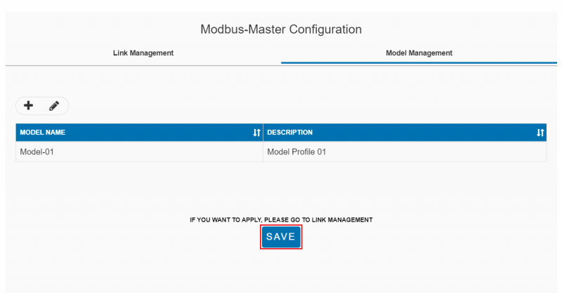
Step 5. Click "Save" button to save the new model.
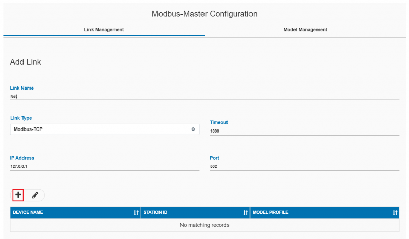
Step 1. From Modbus-Master Configuration, open Link Management tab, click "+" to add a new Link.
Step 2. Input Link Name, Link Type for the new Link.
for Modbus-RTU link, set parameters: - COM port - Baudrate - Data bits - Stop bits - Parity mode
Click "+" icon to add a new device.
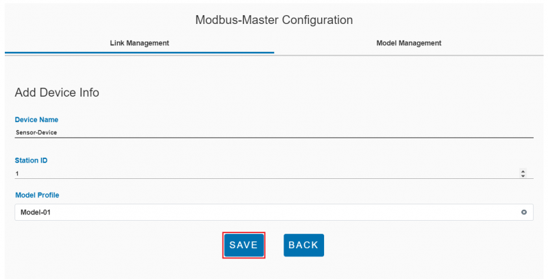
Step 3. Input Device Name, Station Id and select Model Profile for the new device. Model Profile should be added by upper Model Management steps.
Click "Save" button to save the new device.
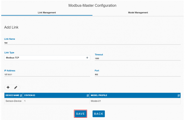
Step 4. Click "Save" button to save the new link.
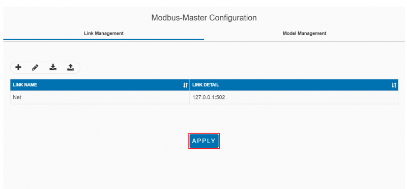
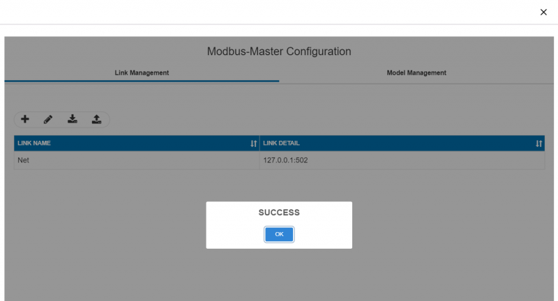
Step 5. Click "Apply" button to apply the new link.
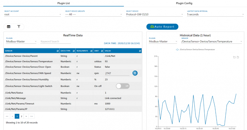
Step 6. Go to Plugin List and select Modbus-Master plugin, the new sensor will be shown in this page
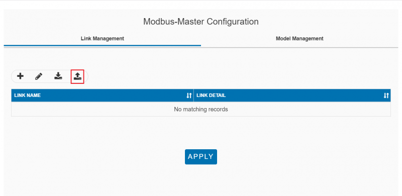
Step 1. Click Import button from Modbus-Master Configuration
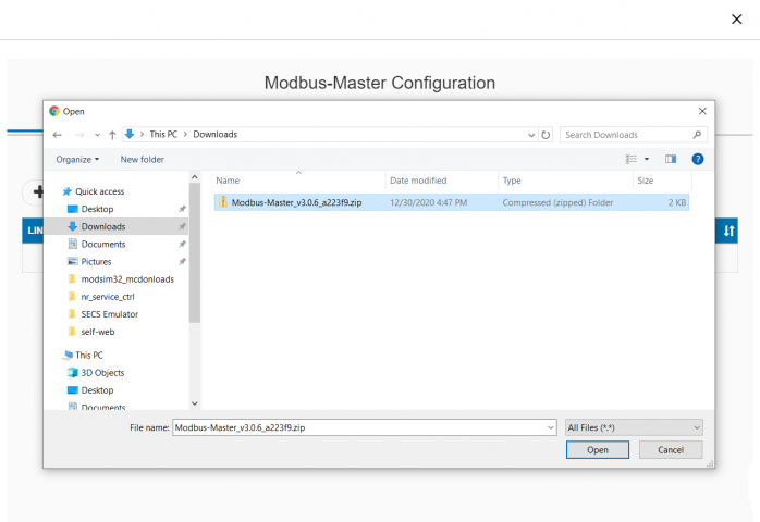
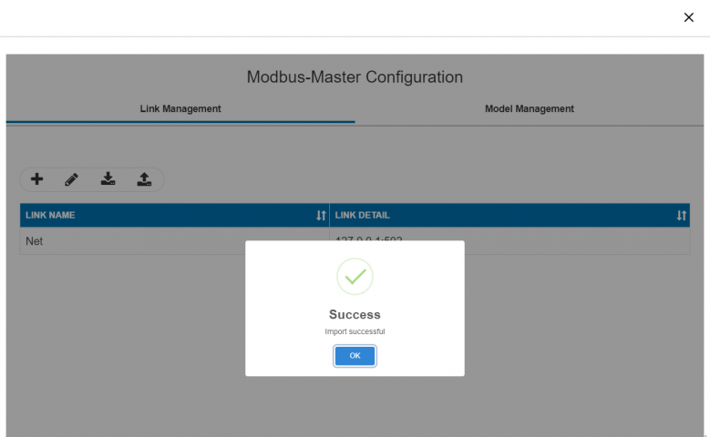
Step 2. Select target file you like to import
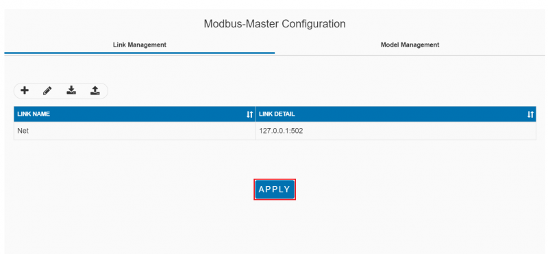
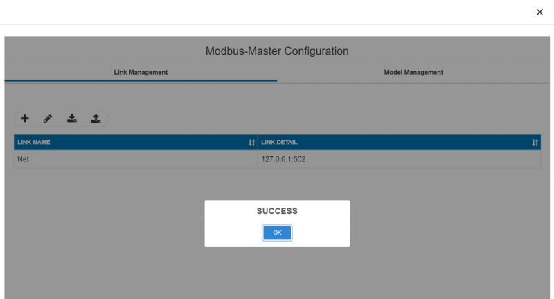
Step 3. Click APPLY to use imported configuration
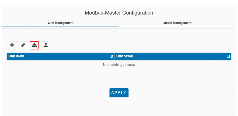
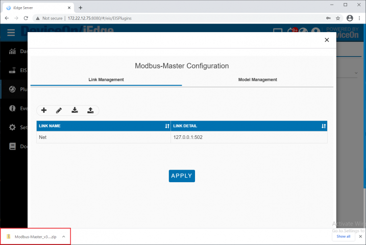
Step 1. Click Export button from Modbus-Master Configuration
Step 2. Explore the exported file
Use Modsim32 to simulate a modbus TCP device with a temperature sensor and a humidity sensor, config Modbus-Master to read these two sensors and upload iEdge cloud.
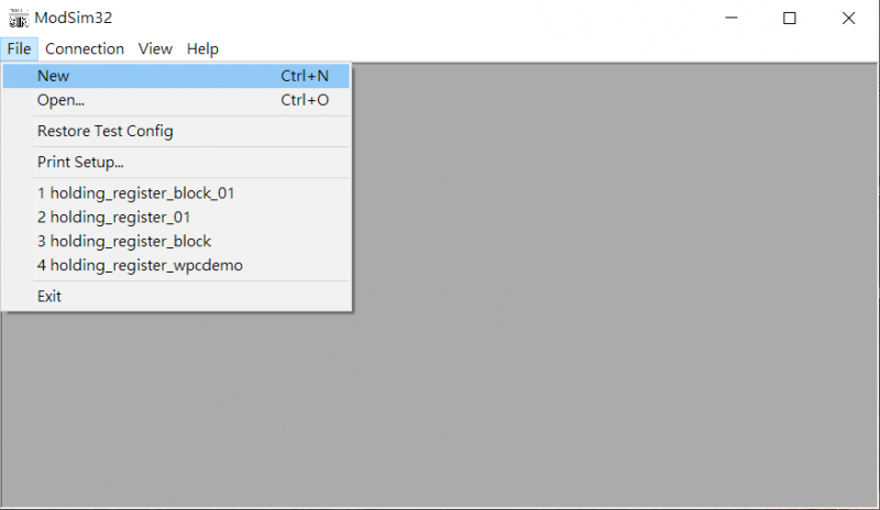
Step1. Open Modbus Simulator: Launch ModSim32 and click "New" in program menu to create a new simulator page.
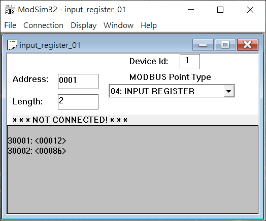
Step2. Set parameter as below:
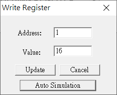
Step3. Enable Auto Simulation:
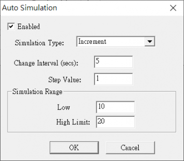
Step4. Set simulation parameters:
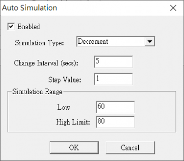
Step5. Do the same step for the address 30002 and set simulation parameter as below:
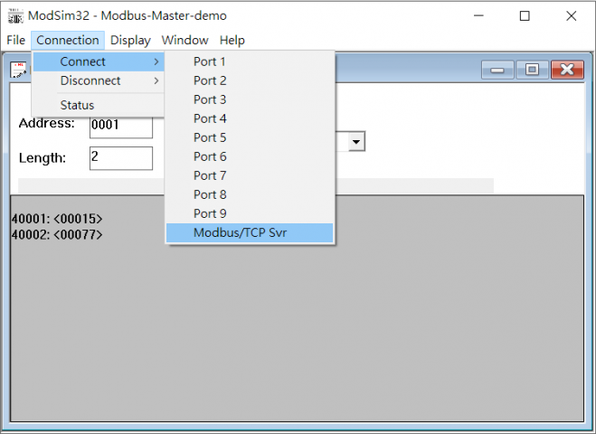
Step6. Set Connection to Modbus/TCP Svr:
Step7. Config Modbus-Master
