Difference between revisions of "ROM-5722 user guide"
Jems.cheng (talk | contribs) |
|||
| (49 intermediate revisions by 2 users not shown) | |||
| Line 1: | Line 1: | ||
| − | |||
| − | + | | |
| − | |||
| − | |||
| − | |||
| − | |||
| − | |||
| − | |||
| − | = | + | = 產品介紹 = |
| − | + | == '''產品特性(Features)''' == | |
| − | == '''接口布局和尺寸(Layout and Sizes)''' | + | *NXP Arm® Cortex®-A53 i.MX8M Plus Quad/Dual up to 1.8 GHz |
| + | *1 x Arm Cortex-M7 core | ||
| + | *Onboard LPDDR4 6 GB, 4000MT/s memory | ||
| + | *1 x 4 lane MIPI-CSI,1 x Dual channel LVDS or 1 x Display Port | ||
| + | *4 x USB2.0, 1 x USB 2.0 OTG, 4 x UART, 5 x I2C, 14 x GPIO, 1 x PCIe3.0, 2 x Gigabit LAN, 2 x CAN-FD | ||
| + | *Neural network accelerator up to 2.3 TOPS | ||
| + | *Supports Ycoto Linux and Android | ||
| + | |||
| + | == '''產品官網連結(Product information Link)''' == | ||
| + | |||
| + | [https://www.advantech.com/zh-tw/products/77b59009-31a9-4751-bee1-45827a844421/rom-5722/mod_11aa0c77-868e-4014-8151-ac7a7a1c5c1b '''ROM-5722'''] | ||
| + | |||
| + | = '''接口布局和尺寸(Layout and Sizes)''' = | ||
=== '''ROM-5722 接口布局圖 Board Dimension Layout ''' === | === '''ROM-5722 接口布局圖 Board Dimension Layout ''' === | ||
| Line 19: | Line 24: | ||
[[File:ROM-5722 module 2021-10-20 155940.jpg|RTENOTITLE]] | [[File:ROM-5722 module 2021-10-20 155940.jpg|RTENOTITLE]] | ||
| + | [[File:ROM-5722 SW1.png|RTENOTITLE]] | ||
| + | === '''SOM-DB2510 接口布局圖 Board Dimension Layout''' === | ||
| − | + | [[File:SOM-DB2510.PNG|RTENOTITLE]] | |
| − | |||
| − | |||
| − | |||
| − | [[File: | ||
| + | | ||
| + | [[File:SOM-DB2510 IO.PNG|RTENOTITLE]] | ||
=== '''主板内置插针式引脚排序方式 (Pin Header defination) ''' === | === '''主板内置插针式引脚排序方式 (Pin Header defination) ''' === | ||
| Line 33: | Line 38: | ||
=== '''Internal I/O''' === | === '''Internal I/O''' === | ||
| − | [[File: | + | [[File:SOM-DB2510 connect1.PNG|RTENOTITLE]] |
| − | {| border="1" cellspacing="1" | + | [[File:SOM-DB2510 connect2.PNG|RTENOTITLE]] |
| + | |||
| + | {| border="1" cellpadding="1" cellspacing="1" style="width: 763px;" | ||
|- | |- | ||
| − | | ''' | + | | '''Label''' |
| − | | ''' | + | | style="width: 296.422px;" | '''Function''' |
| − | | ''' | + | | style="width: 64px;" | '''Label''' |
| + | | style="width: 301px;" | '''Function''' | ||
|- | |- | ||
| − | | | + | | ATX1 |
| − | | | + | | style="width: 296.422px;" | ATX Connector |
| − | | | + | | style="width: 64px;" | FAN1 |
| + | | style="width: 301px;" | Smart Fan Connector | ||
|- | |- | ||
| − | | | + | | SMARC_IN1 |
| − | | | + | | style="width: 296.422px;" | Wide Range Input Power Connector (3V~5.25V) |
| − | | | + | | style="width: 64px;" | FAN2 |
| + | | style="width: 301px;" | System Fan Connector | ||
|- | |- | ||
| − | | | + | | DCIN1 |
| − | | | + | | style="width: 296.422px;" | DCIN connector |
| − | | | + | | style="width: 64px;" | CAN0_1 |
| + | | style="width: 301px;" | CAN Bus Connector | ||
|- | |- | ||
| − | | | + | | DP0_HDMI |
| − | | | + | | style="width: 296.422px;" | DP & HDMI Connector |
| − | | | + | | style="width: 64px;" | USB0 |
| + | | style="width: 301px;" | USB OTG Connector | ||
|- | |- | ||
| − | | | + | | USB12 |
| − | | | + | | style="width: 296.422px;" | USB 2.0 port1~2 & USB 3.0 port0 Connector |
| − | | | + | | style="width: 64px;" | COM1_3 |
| + | | style="width: 301px;" | COM Port Port1,3 Connector | ||
|- | |- | ||
| − | | | + | | TYPEC_DP1 |
| − | | COM Port | + | | style="width: 296.422px;" | Type-C Connector |
| − | + | | style="width: 64px;" | COM2_4 | |
| + | | style="width: 301px;" | COM Port Port2,4 Connector | ||
|- | |- | ||
| − | | | + | | LAN0_LAN1 |
| − | | | + | | style="width: 296.422px;" | LAN0 & LAN1 Connector |
| − | | | + | | style="width: 64px;" | CN8 |
| + | | style="width: 301px;" | I2C connector for I2C_PM | ||
|- | |- | ||
| − | | | + | | LOUT1 |
| − | | | + | | style="width: 296.422px;" | Line Out Connector |
| − | | | + | | style="width: 64px;" | CN7 |
| + | | style="width: 301px;" | I2C Connector for I2C_GP | ||
|- | |- | ||
| − | | | + | | MIC1 |
| − | | | + | | style="width: 296.422px;" | MIC1 Connector |
| − | | | + | | style="width: 64px;" | CN10 |
| + | | style="width: 301px;" | eSPI Pin Header | ||
|- | |- | ||
| − | | | + | | CN1_MXM1 |
| − | | | + | | style="width: 296.422px;" | SMARC Connector |
| − | | | + | | style="width: 64px;" | SATAP1 |
| + | | style="width: 301px;" | SATA Power Connector | ||
|- | |- | ||
| − | | | + | | PCIEA-X4 |
| − | | | + | | style="width: 296.422px;" | PCIe x4 Connector |
| − | | | + | | style="width: 64px;" | CSI0_B2B |
| + | | style="width: 301px;" | MIPI B2B Connector for 2M Camera | ||
|- | |- | ||
| − | | | + | | SATA1 |
| − | | | + | | style="width: 296.422px;" | SATA Port0 Connector |
| − | | | + | | style="width: 64px;" | CSI1_B2B |
| + | | style="width: 301px;" | MIPI B2B Connector for 8M & 13M Camera | ||
|- | |- | ||
| − | | | + | | PCIED-X1 |
| − | | | + | | style="width: 296.422px;" | PCIe x1 Connector |
| − | | | + | | style="width: 64px;" | SPI_BIOS1 |
| + | | style="width: 301px;" | Carrier Board BIOS Socket (SOIC) | ||
|- | |- | ||
| − | | | + | | M2 |
| − | | M.2 Key E | + | | style="width: 296.422px;" | M.2 Key-E Connector |
| − | | | + | | style="width: 64px;" | BAT1 |
| + | | style="width: 301px;" | Coin battery holder | ||
|- | |- | ||
| − | | | + | | MPCIE_C |
| − | | | + | | style="width: 296.422px;" | Mini PCIe Connector |
| − | | | + | | style="width: 64px;" | BAT2 |
| + | | style="width: 301px;" | Smart battery Connector | ||
|- | |- | ||
| − | | | + | | SIM |
| − | | | + | | style="width: 296.422px;" | SIM card Connector |
| − | | | + | | style="width: 64px;" | LINEOUT_1 |
| + | | style="width: 301px;" | I2S Headphone Connector | ||
|- | |- | ||
| − | | | + | | LVDS1 |
| − | | | + | | style="width: 296.422px;" | LVDS1 Connector |
| − | | | + | | style="width: 64px;" | MIC_1 |
| + | | style="width: 301px;" | I2S MIC In Connector | ||
|- | |- | ||
| − | | | + | | LVDS0 |
| − | | | + | | style="width: 296.422px;" | LVDS0 Connector |
| − | | | + | | style="width: 64px;" | CSI1_FPC |
| + | | style="width: 301px;" | MIPI FPC Connector for 8M & 13M Camera | ||
|- | |- | ||
| − | | | + | | LVDS1_INVERTER |
| − | | | + | | style="width: 296.422px;" | LVDS1 Invertor Connector |
| − | | | + | | style="width: 64px;" | CSI0_FPC |
| + | | style="width: 301px;" | MIPI FPC Connector for 2M Camera | ||
|- | |- | ||
| − | | | + | | LVDS0_INVERTER |
| − | | | + | | style="width: 296.422px;" | LVDS0 Invertor Connector |
| − | | | + | | style="width: 64px;" | CN5 |
| + | | style="width: 301px;" | I2S2 Connector | ||
|- | |- | ||
| − | | | + | | SPI_BIOS2 |
| − | | | + | | style="width: 296.422px;" | Carrier Board BIOS Socket (QFN) |
| − | | | + | | style="width: 64px;" | CN17 |
| + | | style="width: 301px;" | I2S0 Connector | ||
|- | |- | ||
| − | | | + | | SD |
| − | | | + | | style="width: 296.422px;" | SD Card Connector |
| − | | | + | | style="width: 64px;" | |
| + | | style="width: 301px;" | | ||
| + | |} | ||
| + | |||
| + | | ||
| + | |||
| + | === '''Rear I/O ''' === | ||
| + | |||
| + | [[File:SOM-DB2510 IO.PNG|RTENOTITLE]] | ||
| + | |||
| + | === '''Jumper 位置( Jumper Locations) ''' === | ||
| + | |||
| + | [[File:DB-2510 JumperLocations1.PNG|RTENOTITLE]] | ||
| + | |||
| + | [[File:DB-2510 JumperLocations2.PNG|RTENOTITLE]] | ||
| + | |||
| + | {| border="1" cellpadding="1" cellspacing="1" style="width: 850px;" | ||
|- | |- | ||
| − | | | + | | Lable |
| − | | | + | | style="width: 330px;" | Function |
| − | | | + | | style="width: 53px;" | Lable |
| + | | style="width: 305px;" | Function | ||
| + | |- | ||
| + | | BTN3 | ||
| + | | style="width: 330px;" | Sleep Button | ||
| + | | style="width: 53px;" | J14 | ||
| + | | style="width: 305px;" | EDP1/LVDS1 Hot-Plug Detect Selection Header | ||
| + | |- | ||
| + | | BTN1 | ||
| + | | style="width: 330px;" | Power Button | ||
| + | | style="width: 53px;" | J56 | ||
| + | | style="width: 305px;" | Standby Voltage Control Header | ||
| + | |- | ||
| + | | BTN2 | ||
| + | | style="width: 330px;" | Reset Button | ||
| + | | style="width: 53px;" | J44 | ||
| + | | style="width: 305px;" | Module +3.3V/+5V Power Selection Header | ||
| + | |- | ||
| + | | SW4 | ||
| + | | style="width: 330px;" | BOOT SELECT Switch | ||
| + | | style="width: 53px;" | PSON1 | ||
| + | | style="width: 305px;" | AT/ATX Selection Header | ||
| + | |- | ||
| + | | LID1 | ||
| + | | style="width: 330px;" | LID Switch | ||
| + | | style="width: 53px;" | SPI_CN1 | ||
| + | | style="width: 305px;" | SPI Header | ||
| + | |- | ||
| + | | J30 | ||
| + | | style="width: 330px;" | Enable Battery Low# Header | ||
| + | | style="width: 53px;" | CN14 | ||
| + | | style="width: 305px;" | For CAN Bus port0 Terminal Resistor | ||
| + | |- | ||
| + | | M2E_DISABLE_N1 | ||
| + | | style="width: 330px;" | M.2 Wireless Disable | ||
| + | | style="width: 53px;" | CN15 | ||
| + | | style="width: 305px;" | For CAN Bus port1 Terminal Resistor | ||
| + | |- | ||
| + | | J29 | ||
| + | | style="width: 330px;" | SMB Alert Enable Header | ||
| + | | style="width: 53px;" | J3/J4 | ||
| + | | style="width: 305px;" | DP0 EQ0 Selection | ||
| + | |- | ||
| + | | CN9 | ||
| + | | style="width: 330px;" | Header For GPIO Test | ||
| + | | style="width: 53px;" | J5/J6 | ||
| + | | style="width: 305px;" | DP0 EQ1 Selection | ||
| + | |- | ||
| + | | J7/J8 | ||
| + | | style="width: 330px;" | LVDS0 Power Selection Header | ||
| + | | style="width: 53px;" | J58 | ||
| + | | style="width: 305px;" | PCIE_B_CKREQ# Selection | ||
| + | |- | ||
| + | | J11/J12 | ||
| + | | style="width: 330px;" | LVDS1 Power Selection Header | ||
| + | | style="width: 53px;" | J59 | ||
| + | | style="width: 305px;" | PCIE_A_CKREQ# Selection | ||
| + | |- | ||
| + | | J9 | ||
| + | | style="width: 330px;" | LVDS0 Inverter Power Selection Heade | ||
| + | | style="width: 53px;" | GPIO_0 | ||
| + | | style="width: 305px;" | GPIO0/CAM0_PWR# Selection | ||
|- | |- | ||
| − | | | + | | J10 |
| − | | LVDS0 | + | | style="width: 330px;" | EDP0/LVDS0 Hot-Plug Detect Selection Header |
| − | | | + | | style="width: 53px;" | GPIO_1 |
| + | | style="width: 305px;" | GPIO1/CAM1_PWR# Selection | ||
|- | |- | ||
| − | | | + | | J26 |
| − | | | + | | style="width: 330px;" | HDA/I2S Selection Header |
| − | | | + | | style="width: 53px;" | GPIO_2 |
| + | | style="width: 305px;" | GPIO2/CAM0_RST# Selection | ||
|- | |- | ||
| − | | | + | | J1 |
| − | | | + | | style="width: 330px;" | DP1/HDMI1 Select |
| − | | | + | | style="width: 53px;" | GPIO_3 |
| + | | style="width: 305px;" | GPIO3/CAM1_RST# Selection | ||
|- | |- | ||
| − | | | + | | J13 |
| − | | | + | | style="width: 330px;" | LVDS1 Inverter Power Selection Header |
| − | | | + | | style="width: 53px;" | GPIO_4 |
| + | | style="width: 305px;" | GPIO4/HDA_RST# Selection | ||
|- | |- | ||
| − | | | + | | J31 |
| − | | | + | | style="width: 330px;" | Clear CMOS Header |
| − | | | + | | style="width: 53px;" | GPIO_5 |
| + | | style="width: 305px;" | GPIO5/PWM_OUT Selection | ||
|- | |- | ||
| − | | | + | | J25 |
| − | | | + | | style="width: 330px;" | SPI Power Header |
| − | | | + | | style="width: 53px;" | GPIO_6 |
| + | | style="width: 305px;" | GPIO6/TACHIN Selection | ||
|- | |- | ||
| − | | | + | | SW1 |
| − | | | + | | style="width: 330px;" | COM1 mode Select |
| − | | | + | | style="width: 53px;" | SATA_ACT_PH1 |
| + | | style="width: 305px;" | SATA act# Header | ||
|- | |- | ||
| − | | | + | | SW2 |
| − | | | + | | style="width: 330px;" | COM3 mode Select |
| − | | | + | | style="width: 53px;" | PWRBTN_PH1 |
| + | | style="width: 305px;" | Power button Header | ||
|- | |- | ||
| − | | | + | | J41 |
| − | | | + | | style="width: 330px;" | Core Power Voltage Control Header |
| − | | | + | | style="width: 53px;" | SYS_RESET_PH1 |
| + | | style="width: 305px;" | Reset button Header | ||
|- | |- | ||
| − | | | + | | J2 |
| − | | | + | | style="width: 330px;" | DDI1 AUX/DDC Selection |
| − | | | + | | style="width: 53px;" | |
| + | | style="width: 305px;" | | ||
|} | |} | ||
| + | === '''LED Function List ''' === | ||
| − | + | {| border="1" cellpadding="1" cellspacing="1" style="width: 500px;" | |
| − | + | |- | |
| − | + | | Location | |
| − | + | | Function | |
| − | + | |- | |
| − | {| border="1" cellspacing="1" | + | | MODULE_VIN_LED1 |
| + | | WDT_TIME_OUT# Indicate | ||
| + | |- | ||
| + | | MODULE_5V_LED | ||
| + | | Module 5V Indicate | ||
| + | |- | ||
| + | | MODULE_VIN_LED | ||
| + | | Module +V_MOD_IN Indicate | ||
| + | |- | ||
| + | | RESET_OUT_LED | ||
| + | | RESET_OUT Indicate | ||
|- | |- | ||
| − | | | + | | RESET_OUT_LED |
| − | | | + | | CARRIER_STBY Indicate |
| − | |||
|- | |- | ||
| − | | | + | | CARRIER_PWR_ON_LED |
| − | | | + | | CARRIER_PWR_ON Indicate |
| − | |||
|- | |- | ||
| − | | | + | | MODULE_3P3V_LED |
| − | | | + | | Module 3.3V Indicate |
| − | |||
|- | |- | ||
| − | | | + | | 3P3V_LED |
| − | | | + | | Carrier Board +V3.3 Indicate |
| − | |||
|- | |- | ||
| − | | | + | | 5V_LED |
| − | | | + | | Carrier Board +V5 Indicate |
| − | |||
|- | |- | ||
| − | | | + | | 5V_DUAL_LED |
| − | | | + | | Carrier Board +V5SB Indicate |
| − | |||
|- | |- | ||
| − | | | + | | 3P3V_DUAL_LED |
| − | | | + | | Carrier Board +V3.3SB Indicate |
| − | |||
|- | |- | ||
| − | | | + | | 5VA_LED |
| − | | | + | | Carrier Board +V5D_MOD Indicate |
| − | |||
|- | |- | ||
| − | | | + | | SATA_LED |
| − | | | + | | SATA Indicate |
| − | |||
|- | |- | ||
| − | | | + | | SOM_LED |
| − | | | + | | SOM BOM Indicate |
| − | |||
|- | |- | ||
| − | | | + | | RISC_LED |
| − | | | + | | RISC BOM Indicate |
| − | |||
|} | |} | ||
| − | === | + | === '''Switch Settings''' === |
| + | |||
| + | *[[SW4|SW4]] (Boot Select/Force Recovery/Test Switches) | ||
| + | *[[LID1|LID1]] (LID Button Enable/Disable Switches) | ||
| + | *[[SW5|SW5 ]](LAN CONN LED Pull High Switches) | ||
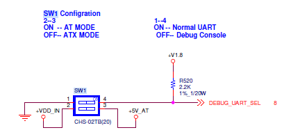
| + | *[[COM0_Settings|SW1]](COM0 Settings) | ||
| + | *[[SW2|SW2]](COM2 Settings) | ||
| + | *[[I2S_Clock_Settings|SW3 ]](I2S Clock Settings) | ||
| + | *[[M2E_DISABLE_N1|M2E_DISABLE_N1]](M.2 Wireless Disable Switch) | ||
| + | |||
| + | === '''接口引脚定義 (Connector Pin definitions)''' === | ||
| − | + | *[[ATX1_Pin_Connector| ATX1 Pin Connector]] | |
| + | *[[SMARC_IN1_Pin_Connectors|SMARC_IN1 Pin Connectors]] | ||
| + | *[[BAT1_RTC_Battery_Connectors|BAT1 RTC Battery Connectors]] | ||
| + | *[[DCIN1_DC-IN_Power_Connectors|DCIN1 DC-IN Power Connectors]] | ||
| + | *[[CAN0_1_CAN_Bus_Connectors|CAN0_1 CAN Bus Connectors]] | ||
| + | *[[CN9_GPIO_Headers|CN9 GPIO Headers]] | ||
| + | *[[COM2_4_COM_Port2&4_Connectors|COM2_4 COM Port2&4 Connectors]] | ||
| + | *[[COM1_3_COM_Port1&_3_Connectors|COM1_3 COM Port1& 3 Connectors]] | ||
| + | *[[CN10_ESPI_Headers|CN10 ESPI Headers]] | ||
| + | *[[LVDS0_LVDS_Connectors|LVDS0 LVDS Connectors]] | ||
| + | *[[LVDS0_INVERTER_LVDS_INVERTER_Connectors|LVDS0_INVERTER LVDS INVERTER Connectors]] | ||
| + | *[[LVDS1_LVDS_Connectors|LVDS1 LVDS Connectors]] | ||
| + | *[[LVDS1_INVERTER_LVDS_INVERTER_Connectors|LVDS1_INVERTER LVDS INVERTER Connectors]] | ||
| + | *[[CN7_I2C_GP_Connectors|CN7 I2C_GP Connectors]] | ||
| + | *[[SPI_CN1_SPI_Connectors|SPI_CN1 SPI Connectors]] | ||
| + | *[[SATAP1_SATA_PWR_Connectors|SATAP1 SATA PWR Connectors]] | ||
| + | *[[CSI0_FPC_Connectors|CSI0_FPC Connectors]] | ||
| + | *[[CSI1_FPC_Connectors|CSI1_FPC Connectors]] | ||
| + | *[[CN5_I2S2_Connectors|CN5 I2S2 Connectors]] | ||
| + | *[[CN17_I2S0_Connectors|CN17 I2S0 Connectors]] | ||
| + | *[[PWRBTN_PH1_PWRBTN_Pin_Headers|PWRBTN_PH1 PWRBTN Pin Headers]] | ||
| + | *[[SYS_RESET_PH1_SYS_RESET_Pin_Headers|SYS_RESET_PH1 SYS RESET Pin Headers]] | ||
| + | *[[SATA_ACT_PH1_SATA_ACT|SATA_ACT_PH1 SATA ACT# Pin Headers]] | ||
| + | *[[J32_Power_LED_Pin_Headers|J32 Power LED Pin Headers]] | ||
| + | *[[J30_BATLOW_Pin_Headers|J30 BATLOW Pin Headers]] | ||
| + | *[[J29_SMBUS_Alert_Pin_Headers|J29 SMBUS Alert Pin Headers]] | ||
| + | *[[J41_Core_Power_Controls|J41 Core Power Controls]] | ||
| + | *[[PSON1_ATX/AT_Mode_Selection|PSON1 ATX/AT Mode Selection]] | ||
| + | *[[J56_Standby_Power_Controls|J56 Standby Power Controls]] | ||
| + | *[[J44_Module_Power_Settings|J44 Module Power Settings]] | ||
| + | *[[J7,J8_LVDS0_Power_Selection|J7,J8 LVDS0 Power Selection]] | ||
| + | *[[J9_LVDS0_Inverter_Power_Selection|J9 LVDS0 Inverter Power Selection]] | ||
| + | *[[J11,J12_LVDS1_Power_Selection|J11,J12 LVDS1 Power Selection]] | ||
| + | *[[LVDS1_Inverter_Power_Selection|LVDS1 Inverter Power Selection]] | ||
| + | *[[EDP0_/LVDS0_HPD_Selection|EDP0 /LVDS0 HPD Selection]] | ||
| + | *[[J14_EDP1/LVDS1_HPD_Selection|J14 EDP1/LVDS1 HPD Selection]] | ||
| + | *[[CN14_CAN0_Terminal_Resistor_Selection|CN14 CAN0 Terminal Resistor Selection]] | ||
| + | *[[CN15_CAN1_Terminal_Resistor_Selection|CN15 CAN1 Terminal Resistor Selection]] | ||
| + | *[[J2_DDI1_AUX/DDC_Selection|J2 DDI1 AUX/DDC Selection]] | ||
| + | *[[J1_DP1/HDMI1_Selection|J1 DP1/HDMI1 Selection]] | ||
| + | *[[J58_PCIE_B_CKREQ|J58 PCIE_B_CKREQ# Selection]] | ||
| + | *[[J59_PCIE_A_CKREQ|J59 PCIE_A_CKREQ# Selection]] | ||
| + | *[[J31_Clear_CMOS|J31 Clear CMOS]] | ||
| + | *[[J25_+V1.8M_SPI_Power_Jumpers|J25 +V1.8M_SPI Power Jumpers]] | ||
| + | *[[GPIO_0_GPIO0_Settings|GPIO_0 GPIO0 Settings]] | ||
| + | *[[GPIO_1_GPIO1_Settings|GPIO_1 GPIO1 Settings]] | ||
| + | *[[GPIO_2_GPIO2_Settings|GPIO_2 GPIO2 Settings]] | ||
| + | *[[GPIO_3_GPIO3_Settings|GPIO_3 GPIO3 Settings]] | ||
| + | *[[GPIO_4_GPIO4_Settings|GPIO_4 GPIO4 Settings]] | ||
| + | *[[GPIO_5_GPIO5_Settings|GPIO_5 GPIO5 Settings]] | ||
| + | *[[GPIO_6_GPIO6_Settings|GPIO_6 GPIO6 Settings]] | ||
| + | *[[J26_HDA/I2S_Selection|J26 HDA/I2S Selection]] | ||
| − | + | | |
| − | |||
| − | |||
| − | |||
| − | |||
| − | |||
| − | |||
| − | |||
| − | |||
| − | |||
=== '''机械尺寸 ('''Mechanical Characteristics) === | === '''机械尺寸 ('''Mechanical Characteristics) === | ||
| − | '''ROM- | + | '''ROM-5722''' |
'''[[File:ROM-5620 Mechanical Specifications1.jpg|RTENOTITLE]]''' | '''[[File:ROM-5620 Mechanical Specifications1.jpg|RTENOTITLE]]''' | ||
| Line 250: | Line 418: | ||
'''[[File:ROM-5620 Mechanical Specifications2.jpg|RTENOTITLE]]''' | '''[[File:ROM-5620 Mechanical Specifications2.jpg|RTENOTITLE]]''' | ||
| + | | ||
| + | | ||
| + | | ||
| + | ---- | ||
| + | | ||
| − | + | = '''快速入门 (Quick Start)''' = | |
| − | |||
| − | |||
| − | |||
=== '''系统下载 (OS Download)''' === | === '''系统下载 (OS Download)''' === | ||
| − | *'''Linux系统 (Linux OS)'''''' ''' | + | *'''Linux系统 (Linux OS)'''''' ''' |
'''Yocto 3.0:'''[[IoTGateway/BSP/Linux/iMX8/OS_Support_List_3.0|IoTGateway/BSP/Linux/iMX8/OS Support List 3.0]] | '''Yocto 3.0:'''[[IoTGateway/BSP/Linux/iMX8/OS_Support_List_3.0|IoTGateway/BSP/Linux/iMX8/OS Support List 3.0]] | ||
---- | ---- | ||
| + | |||
| + | | ||
=== '''Linux 燒錄方法 (Linux Flash eMMC Method)''' === | === '''Linux 燒錄方法 (Linux Flash eMMC Method)''' === | ||
| Line 277: | Line 449: | ||
Step1: 創造一張可開機的SD 卡 (Create a bootable SD card) | Step1: 創造一張可開機的SD 卡 (Create a bootable SD card) | ||
| + | |||
| + | <span style="font-size:small;">Command :</span> | ||
| + | |||
| + | <span style="font-size:small;">'''sudo dd if=5722A1AIM30LIVA0271_iMX8MP_6G_2021-06-19.img of=/dev/sdf bs=1M conv=fsync status=progre'''ss </span> | ||
[[File:Z24.jpg|RTENOTITLE]] | [[File:Z24.jpg|RTENOTITLE]] | ||
| Line 282: | Line 458: | ||
Step2: 將可開機的SD 卡插入底板SD卡卡槽(Plug the SD card into Carrier board 's SD card slot) | Step2: 將可開機的SD 卡插入底板SD卡卡槽(Plug the SD card into Carrier board 's SD card slot) | ||
| − | [[File: | + | [[File:SOM-DB2510 SD Card slot sd boot.PNG|RTENOTITLE]] |
Step4: 確認開機選擇指撥開關 | Step4: 確認開機選擇指撥開關 | ||
| − | SD 卡開機模式: | + | SD 卡開機模式: (2, 3:on, others off) |
| − | | + | eMMC 開機模式: (1: on, others off) |
| + | [[File:SOM-DB2510 SD switch setting.PNG|RTENOTITLE]] | ||
| + | | ||
Step3:打開電源 和 終端機 (Turn on the Power & Terminal) | Step3:打開電源 和 終端機 (Turn on the Power & Terminal) | ||
| Line 298: | Line 476: | ||
Step4: 解壓縮flash tools 檔案,並複製到U盤中(Unzip the flash tools file , then copy to USB Disk) | Step4: 解壓縮flash tools 檔案,並複製到U盤中(Unzip the flash tools file , then copy to USB Disk) | ||
| − | + | | |
解壓縮(Unzip the file ) | 解壓縮(Unzip the file ) | ||
| Line 322: | Line 500: | ||
5. 將U盤連接到ROM-5722系統, 進入flsah tool下的mk_inand資歷夾, 執行指令./mksd-linux.sh /dev/mmcblk2燒錄image到eMMC(Connect USB Disk to ROM-5722 system, browser to mk_inand folder and execute flash shell script "./mksd-linux.sh /dev/mmcblk2" | 5. 將U盤連接到ROM-5722系統, 進入flsah tool下的mk_inand資歷夾, 執行指令./mksd-linux.sh /dev/mmcblk2燒錄image到eMMC(Connect USB Disk to ROM-5722 system, browser to mk_inand folder and execute flash shell script "./mksd-linux.sh /dev/mmcblk2" | ||
| − | {| border="1" | + | {| border="1" cellpadding="1" cellspacing="1" style="width:500px;" |
|- | |- | ||
| ROM-5722 | | ROM-5722 | ||
| − | | | + | | |
|- | |- | ||
| SD card | | SD card | ||
| Line 339: | Line 517: | ||
| | ||
| + | |||
| + | | ||
=== '''Debug 串口調試 (Debug port Setting)''' === | === '''Debug 串口調試 (Debug port Setting)''' === | ||
| + | |||
| + | '''Debug port output:''' | ||
| + | |||
| + | {| border="1" cellpadding="1" cellspacing="1" style="width: 576px;" | ||
| + | |- | ||
| + | | ROM-5722 CPU | ||
| + | | style="width: 182px;" | ROM-5722 golden finger | ||
| + | | style="width: 135px;" | DB5901 | ||
| + | | style="width: 131px;" | DB2510 | ||
| + | |- | ||
| + | | UART1 | ||
| + | | style="width: 182px;" | SER2 | ||
| + | | style="width: 135px;" | CN15B down | ||
| + | | style="width: 131px;" | COM3 | ||
| + | |- | ||
| + | | UART2: A53 | ||
| + | | style="width: 182px;" | SER3 | ||
| + | | style="width: 135px;" | COM3 | ||
| + | | style="width: 131px;" | COM4 | ||
| + | |- | ||
| + | | UART3 | ||
| + | | style="width: 182px;" | SER0 | ||
| + | | style="width: 135px;" | CN15A up | ||
| + | | style="width: 131px;" | COM1 | ||
| + | |- | ||
| + | | UART4: M7 | ||
| + | | style="width: 182px;" | SER1 | ||
| + | | style="width: 135px;" | COM1 | ||
| + | | style="width: 131px;" | COM2 | ||
| + | |} | ||
以 Tera Term 为例介绍如何使用串口调试功能 | 以 Tera Term 为例介绍如何使用串口调试功能 | ||
| Line 349: | Line 559: | ||
Flow Control流控:无</pre> | Flow Control流控:无</pre> | ||
| − | : | + | : |
Tera Term Tool | Tera Term Tool | ||
| Line 365: | Line 575: | ||
Debug port connection (串口連接) | Debug port connection (串口連接) | ||
| − | [[File: | + | [[File:SOM-DB2510 Debug port.PNG|RTENOTITLE]] |
| − | |||
| + | | ||
Log into Terminal Tool (进入串口调试终端): | Log into Terminal Tool (进入串口调试终端): | ||
| Line 373: | Line 583: | ||
[[File:Z31.jpg|RTENOTITLE]] | [[File:Z31.jpg|RTENOTITLE]] | ||
| − | + | | |
| − | + | = '''Linux系统的基本使用(Linux System Basic Operating Method)''' = | |
| + | |||
| + | === '''UUU 使用方法(USB Connection (OTG port))''' === | ||
Download uuu tool from (Release [[https://github.com/ADVANTECH-Corp/uuu/releases/tag/v20200619 ADV]v20210429 · ADVANTECH-Corp/uuu · GitHub]) or in the folder. | Download uuu tool from (Release [[https://github.com/ADVANTECH-Corp/uuu/releases/tag/v20200619 ADV]v20210429 · ADVANTECH-Corp/uuu · GitHub]) or in the folder. | ||
| Line 393: | Line 605: | ||
[[File:Z34.jpg|RTENOTITLE]] | [[File:Z34.jpg|RTENOTITLE]] | ||
| − | === ''' | + | === '''Display Setting (ROM-5722)''' === |
| + | |||
| + | '''Ex: ''' | ||
| + | <pre>setenv fdtfile imx8mp-rom5722-a1-lvds0-auo.dtb</pre> | ||
''' U-boot Command :''' | ''' U-boot Command :''' | ||
| − | *Display | + | *Display |
| − | **HDMI (default) | + | **HDMI (default) |
| − | ***imx8mp-rom5722-a1.dtb | + | ***imx8mp-rom5722-a1.dtb |
| − | **LVDS | + | **LVDS |
| − | ***g070vw01(LVDS0) + HDMI | + | ***g070vw01(LVDS0) + HDMI |
| − | ****imx8mp-rom5722-a1-lvds0-auo.dtb | + | ****imx8mp-rom5722-a1-lvds0-auo.dtb |
| − | ***g070vw01(LVDS1) + HDMI | + | ***g070vw01(LVDS1) + HDMI |
| − | ****imx8mp-rom5722-a1-lvds1-auo.dtb | + | ****imx8mp-rom5722-a1-lvds1-auo.dtb |
| − | ***g215hvn01(DUAL LVDS) + HDMI | + | ***g215hvn01(DUAL LVDS) + HDMI |
| − | ****imx8mp-rom5722-a1-lvds-dual.dtb | + | ****imx8mp-rom5722-a1-lvds-dual.dtb |
| − | **DSI | + | **DSI |
| − | ***adv7535(DSI to HDMI) + HDMI | + | ***adv7535(DSI to HDMI) + HDMI |
| − | ****imx8mp-rom5722-a1-adv7535.dtb | + | ****imx8mp-rom5722-a1-adv7535.dtb |
| − | ***auog101uan02(DSI) + HDMI | + | ***auog101uan02(DSI) + HDMI |
| − | ****imx8mp-rom5722-a1-auog101uan02.dtb | + | ****imx8mp-rom5722-a1-auog101uan02.dtb |
| − | *Camera | + | *Camera |
| − | **OV5640 (default) | + | **OV5640 (default) |
| − | ***imx8mp-rom5722-a1.dtb | + | ***imx8mp-rom5722-a1.dtb |
| − | **Basler camrea | + | **Basler camrea |
| − | ***imx8mp-rom5722-a1-basler.dtb | + | ***imx8mp-rom5722-a1-basler.dtb |
=== '''乙太網路使用方法(Ethernent Testing Method)''' === | === '''乙太網路使用方法(Ethernent Testing Method)''' === | ||
| Line 475: | Line 690: | ||
[[File:Z39.jpg|RTENOTITLE]] | [[File:Z39.jpg|RTENOTITLE]] | ||
| − | + | | |
<pre>Loop-back Test (Take GPIO0 and GPIO2 as examples) | <pre>Loop-back Test (Take GPIO0 and GPIO2 as examples) | ||
| Line 513: | Line 728: | ||
[[File:SW6&7settingn.jpeg|RTENOTITLE]] | [[File:SW6&7settingn.jpeg|RTENOTITLE]] | ||
| − | MODE1 MODE0<br/> 0 0 LOOPBACK<br/> 0 1 RS232<br/> 1 0 RS485<br/> 1 1 RS422 | + | MODE1 MODE0<br/> 0 0 LOOPBACK<br/> 0 1 RS232<br/> 1 0 RS485<br/> 1 1 RS422 |
| − | Loopback test (eg. ttymxc0)<br/>Connect loopback test tool | + | Loopback test (eg. ttymxc0)<br/> Connect loopback test tool |
| − | #stty ‐F /dev/ttymxc0 115200<br/># stty ‐F /dev/ttymxc0 ‐echo<br/># cat /dev/ttymxc0 &<br/># echo test > /dev/ttymxc0 | + | #stty ‐F /dev/ttymxc0 115200<br/> # stty ‐F /dev/ttymxc0 ‐echo<br/> # cat /dev/ttymxc0 &<br/> # echo test > /dev/ttymxc0 |
=== '''蓝牙使用方法(BlueTooth Operating Method)''' === | === '''蓝牙使用方法(BlueTooth Operating Method)''' === | ||
| Line 545: | Line 760: | ||
SSH Remote Log into Device | SSH Remote Log into Device | ||
| − | *SSH远程登录,以putty选择putty.exe(或者使用Xshell、SecureCRT等类似软件) | + | *SSH远程登录,以putty选择putty.exe(或者使用Xshell、SecureCRT等类似软件) |
| − | *需要设置远程设备的IP、通讯端口(默认22)、通讯方式,登录后验证用户名密码 | + | *需要设置远程设备的IP、通讯端口(默认22)、通讯方式,登录后验证用户名密码 |
| − | |||
| + | | ||
[[File:SSHsettingdetail.png|RTENOTITLE]] | [[File:SSHsettingdetail.png|RTENOTITLE]] | ||
| Line 554: | Line 769: | ||
[[File:Z42.jpg|RTENOTITLE]] | [[File:Z42.jpg|RTENOTITLE]] | ||
| − | + | | |
[[File:Z43.jpg|RTENOTITLE]] | [[File:Z43.jpg|RTENOTITLE]] | ||
| Line 560: | Line 775: | ||
[[File:Z44.jpg|RTENOTITLE]] | [[File:Z44.jpg|RTENOTITLE]] | ||
| − | + | | |
| − | === | + | = '''通用方法(General Method)''' = |
| + | |||
| + | === '''查看CPU温度(Check CPU Temperature)''' === | ||
<pre> root@imx8mprom5722a1:/# cat /sys/devices/virtual/thermal/thermal_zone0/temp 44600 | <pre> root@imx8mprom5722a1:/# cat /sys/devices/virtual/thermal/thermal_zone0/temp 44600 | ||
# 或者直接以度爲單位顯示 echo $[$(cat /sys/class/thermal/thermal_zone0/temp)/1000]° >>> 45°</pre> | # 或者直接以度爲單位顯示 echo $[$(cat /sys/class/thermal/thermal_zone0/temp)/1000]° >>> 45°</pre> | ||
| − | === ''' | + | === '''查看CPU频率(Check CPU Frequency)''' === |
<pre> cat /sys/devices/system/cpu/cpu0/cpufreq/cpuinfo_cur_freq | <pre> cat /sys/devices/system/cpu/cpu0/cpufreq/cpuinfo_cur_freq | ||
>> 900000 | >> 900000 | ||
| Line 573: | Line 790: | ||
>> 1200000</pre> | >> 1200000</pre> | ||
| − | === ''' | + | === '''查看内存容量(Check Memory Capacity)''' === |
<pre>root@imx8mprom5722a1:~# busybox free -m | <pre>root@imx8mprom5722a1:~# busybox free -m | ||
total used free shared buff/cache available | total used free shared buff/cache available | ||
| Line 580: | Line 797: | ||
</pre> | </pre> | ||
| − | === ''' | + | === '''查看存储容量(Check Storage Capacity)''' === |
<pre>root@imx8mprom5722a1:~# busybox df -h | <pre>root@imx8mprom5722a1:~# busybox df -h | ||
Filesystem Size Used Available Use% Mounted on | Filesystem Size Used Available Use% Mounted on | ||
| Line 596: | Line 813: | ||
root@imx8mprom5722a1:~#</pre> | root@imx8mprom5722a1:~#</pre> | ||
| − | === ''' | + | === '''網路Ping測試(Ping Network Testing)''' === |
<pre> ping 8.8.8.8 | <pre> ping 8.8.8.8 | ||
PING 8.8.8.8 (8.8.8.8) 56(84) bytes of data. | PING 8.8.8.8 (8.8.8.8) 56(84) bytes of data. | ||
| Line 602: | Line 819: | ||
64 bytes from 8.8.8.8: icmp_seq=2 ttl=54 time=2.10 ms</pre> | 64 bytes from 8.8.8.8: icmp_seq=2 ttl=54 time=2.10 ms</pre> | ||
| − | === ''' | + | === '''設置RTC (RTC Setting) ''' === |
<pre>root@imx8mprom5722a1:~# systemctl stop ntpdate.service | <pre>root@imx8mprom5722a1:~# systemctl stop ntpdate.service | ||
root@imx8mprom5722a1:~# date 090816072021 && hwclock -w && date | root@imx8mprom5722a1:~# date 090816072021 && hwclock -w && date | ||
| Line 611: | Line 828: | ||
root@imx8mprom5722a1:~#</pre> | root@imx8mprom5722a1:~#</pre> | ||
| − | ''' | + | '''Add Patch in linux-imx_6.1.bb file''' |
| + | <pre>SRC_URI:append:imx8qmrom5722a1 += " file://panel_gpi4.patch"</pre> | ||
| + | |||
| + | | ||
| + | |||
| + | = '''Linux BSP編譯方法(Linux BSP Compile Method)''' = | ||
| − | == '''Linux | + | === [https://ess-wiki.advantech.com.tw/view/IoTGateway/BSP/Linux/iMX8/Yocto_LBVF_User_Guide '''Yocto 5.0'''] === |
| + | |||
| + | === [https://ess-wiki.advantech.com.tw/view/IoTGateway/BSP/Linux/iMX8/Yocto_LBVD_User_Guide '''Yocto 4.2'''] === | ||
| + | |||
| + | === [http://ess-wiki.advantech.com.tw/view/IoTGateway/BSP/Linux/iMX8/Yocto_LBVC_User_Guide '''Yocto 4.0'''] === | ||
=== [http://ess-wiki.advantech.com.tw/view/IoTGateway/BSP/Linux/iMX8/Yocto_LBVA_User_Guide '''Yocto 3.0'''] === | === [http://ess-wiki.advantech.com.tw/view/IoTGateway/BSP/Linux/iMX8/Yocto_LBVA_User_Guide '''Yocto 3.0'''] === | ||
| + | |||
| + | '''============================================================================================================================================''' | ||
| + | |||
| + | | ||
| + | |||
| + | == '''Build known issue''' == | ||
'''如果有驗證上的錯誤 請使用以下的方法''' | '''如果有驗證上的錯誤 請使用以下的方法''' | ||
| Line 691: | Line 923: | ||
ERROR: Task (/home/adv/adv-release-bsp/sources/meta-fsl-bsp-release/imx/meta-bsp/recipes-multimedia/gstreamer/gstreamer 1.0-plugins-base_1.14.imx.bb:do_unpack) failed with exit code '1' | ERROR: Task (/home/adv/adv-release-bsp/sources/meta-fsl-bsp-release/imx/meta-bsp/recipes-multimedia/gstreamer/gstreamer 1.0-plugins-base_1.14.imx.bb:do_unpack) failed with exit code '1' | ||
| − | <u>'''============================================================< | + | <u>'''============================================================'''</u><br/> '''nnshark error ''' |
| + | |||
| + | [https://community.nxp.com/t5/i-MX-Processors/Yocto-3-3-5-10-72-BSP-Build-Fail/m-p/1487902 https://community.nxp.com/t5/i-MX-Processors/Yocto-3-3-5-10-72-BSP-Build-Fail/m-p/1487902] | ||
| + | |||
| + | {| border="0" cellpadding="10" cellspacing="0" style="width:100%;" | ||
| + | |- | ||
| + | | <iframe height="230" key="advonline" level="campaign" path="en/aim-linux_community/" width="100%"></iframe> | ||
| + | |} | ||
Latest revision as of 09:43, 13 June 2025
Contents
- 1 產品介紹
- 2 接口布局和尺寸(Layout and Sizes)
- 2.1 ROM-5722 接口布局圖 Board Dimension Layout
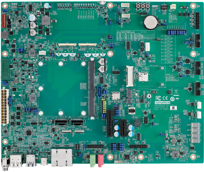
- 2.2 SOM-DB2510 接口布局圖 Board Dimension Layout
- 2.3 主板内置插针式引脚排序方式 (Pin Header defination)
- 2.4 Internal I/O
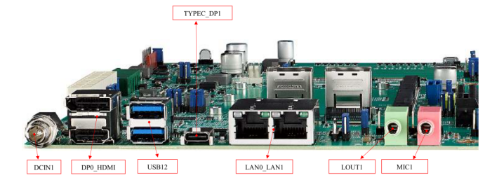
- 2.5 Rear I/O
- 2.6 Jumper 位置( Jumper Locations)
- 2.7 LED Function List
- 2.8 Switch Settings
- 2.9 接口引脚定義 (Connector Pin definitions)
- 2.10 机械尺寸 (Mechanical Characteristics)
- 3 快速入门 (Quick Start)
- 4 Linux系统的基本使用(Linux System Basic Operating Method)
- 4.1 UUU 使用方法(USB Connection (OTG port))
- 4.2 Display Setting (ROM-5722)
- 4.3 乙太網路使用方法(Ethernent Testing Method)
- 4.4 WiFi使用方法(WIFI Testing Method)
- 4.5 4G使用方法(4G Testing Method)
- 4.6 GPIO使用方法(GPIO Operating Method)
- 4.7 串口使用方法(Serial Port Operating Method)
- 4.8 蓝牙使用方法(BlueTooth Operating Method)
- 4.9 遠程訪問及文件傳輸(Remote Access and File Transimmion)
- 5 通用方法(General Method)
- 6 Linux BSP編譯方法(Linux BSP Compile Method)
產品介紹
產品特性(Features)
- NXP Arm® Cortex®-A53 i.MX8M Plus Quad/Dual up to 1.8 GHz
- 1 x Arm Cortex-M7 core
- Onboard LPDDR4 6 GB, 4000MT/s memory
- 1 x 4 lane MIPI-CSI,1 x Dual channel LVDS or 1 x Display Port
- 4 x USB2.0, 1 x USB 2.0 OTG, 4 x UART, 5 x I2C, 14 x GPIO, 1 x PCIe3.0, 2 x Gigabit LAN, 2 x CAN-FD
- Neural network accelerator up to 2.3 TOPS
- Supports Ycoto Linux and Android
產品官網連結(Product information Link)
接口布局和尺寸(Layout and Sizes)
ROM-5722 接口布局圖 Board Dimension Layout
SOM-DB2510 接口布局圖 Board Dimension Layout
主板内置插针式引脚排序方式 (Pin Header defination)
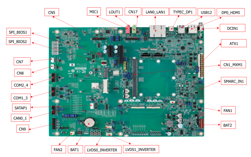
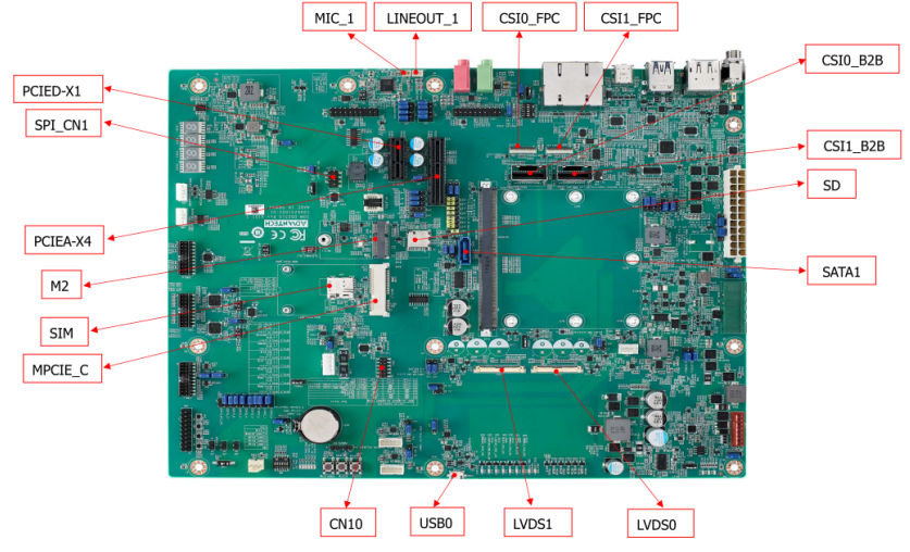
Internal I/O
| Label | Function | Label | Function |
| ATX1 | ATX Connector | FAN1 | Smart Fan Connector |
| SMARC_IN1 | Wide Range Input Power Connector (3V~5.25V) | FAN2 | System Fan Connector |
| DCIN1 | DCIN connector | CAN0_1 | CAN Bus Connector |
| DP0_HDMI | DP & HDMI Connector | USB0 | USB OTG Connector |
| USB12 | USB 2.0 port1~2 & USB 3.0 port0 Connector | COM1_3 | COM Port Port1,3 Connector |
| TYPEC_DP1 | Type-C Connector | COM2_4 | COM Port Port2,4 Connector |
| LAN0_LAN1 | LAN0 & LAN1 Connector | CN8 | I2C connector for I2C_PM |
| LOUT1 | Line Out Connector | CN7 | I2C Connector for I2C_GP |
| MIC1 | MIC1 Connector | CN10 | eSPI Pin Header |
| CN1_MXM1 | SMARC Connector | SATAP1 | SATA Power Connector |
| PCIEA-X4 | PCIe x4 Connector | CSI0_B2B | MIPI B2B Connector for 2M Camera |
| SATA1 | SATA Port0 Connector | CSI1_B2B | MIPI B2B Connector for 8M & 13M Camera |
| PCIED-X1 | PCIe x1 Connector | SPI_BIOS1 | Carrier Board BIOS Socket (SOIC) |
| M2 | M.2 Key-E Connector | BAT1 | Coin battery holder |
| MPCIE_C | Mini PCIe Connector | BAT2 | Smart battery Connector |
| SIM | SIM card Connector | LINEOUT_1 | I2S Headphone Connector |
| LVDS1 | LVDS1 Connector | MIC_1 | I2S MIC In Connector |
| LVDS0 | LVDS0 Connector | CSI1_FPC | MIPI FPC Connector for 8M & 13M Camera |
| LVDS1_INVERTER | LVDS1 Invertor Connector | CSI0_FPC | MIPI FPC Connector for 2M Camera |
| LVDS0_INVERTER | LVDS0 Invertor Connector | CN5 | I2S2 Connector |
| SPI_BIOS2 | Carrier Board BIOS Socket (QFN) | CN17 | I2S0 Connector |
| SD | SD Card Connector |
Rear I/O
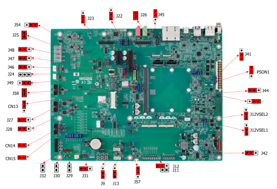
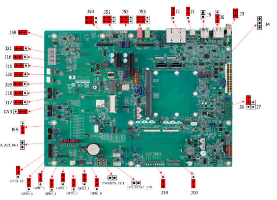
Jumper 位置( Jumper Locations)
| Lable | Function | Lable | Function |
| BTN3 | Sleep Button | J14 | EDP1/LVDS1 Hot-Plug Detect Selection Header |
| BTN1 | Power Button | J56 | Standby Voltage Control Header |
| BTN2 | Reset Button | J44 | Module +3.3V/+5V Power Selection Header |
| SW4 | BOOT SELECT Switch | PSON1 | AT/ATX Selection Header |
| LID1 | LID Switch | SPI_CN1 | SPI Header |
| J30 | Enable Battery Low# Header | CN14 | For CAN Bus port0 Terminal Resistor |
| M2E_DISABLE_N1 | M.2 Wireless Disable | CN15 | For CAN Bus port1 Terminal Resistor |
| J29 | SMB Alert Enable Header | J3/J4 | DP0 EQ0 Selection |
| CN9 | Header For GPIO Test | J5/J6 | DP0 EQ1 Selection |
| J7/J8 | LVDS0 Power Selection Header | J58 | PCIE_B_CKREQ# Selection |
| J11/J12 | LVDS1 Power Selection Header | J59 | PCIE_A_CKREQ# Selection |
| J9 | LVDS0 Inverter Power Selection Heade | GPIO_0 | GPIO0/CAM0_PWR# Selection |
| J10 | EDP0/LVDS0 Hot-Plug Detect Selection Header | GPIO_1 | GPIO1/CAM1_PWR# Selection |
| J26 | HDA/I2S Selection Header | GPIO_2 | GPIO2/CAM0_RST# Selection |
| J1 | DP1/HDMI1 Select | GPIO_3 | GPIO3/CAM1_RST# Selection |
| J13 | LVDS1 Inverter Power Selection Header | GPIO_4 | GPIO4/HDA_RST# Selection |
| J31 | Clear CMOS Header | GPIO_5 | GPIO5/PWM_OUT Selection |
| J25 | SPI Power Header | GPIO_6 | GPIO6/TACHIN Selection |
| SW1 | COM1 mode Select | SATA_ACT_PH1 | SATA act# Header |
| SW2 | COM3 mode Select | PWRBTN_PH1 | Power button Header |
| J41 | Core Power Voltage Control Header | SYS_RESET_PH1 | Reset button Header |
| J2 | DDI1 AUX/DDC Selection |
LED Function List
| Location | Function |
| MODULE_VIN_LED1 | WDT_TIME_OUT# Indicate |
| MODULE_5V_LED | Module 5V Indicate |
| MODULE_VIN_LED | Module +V_MOD_IN Indicate |
| RESET_OUT_LED | RESET_OUT Indicate |
| RESET_OUT_LED | CARRIER_STBY Indicate |
| CARRIER_PWR_ON_LED | CARRIER_PWR_ON Indicate |
| MODULE_3P3V_LED | Module 3.3V Indicate |
| 3P3V_LED | Carrier Board +V3.3 Indicate |
| 5V_LED | Carrier Board +V5 Indicate |
| 5V_DUAL_LED | Carrier Board +V5SB Indicate |
| 3P3V_DUAL_LED | Carrier Board +V3.3SB Indicate |
| 5VA_LED | Carrier Board +V5D_MOD Indicate |
| SATA_LED | SATA Indicate |
| SOM_LED | SOM BOM Indicate |
| RISC_LED | RISC BOM Indicate |
Switch Settings
- SW4 (Boot Select/Force Recovery/Test Switches)
- LID1 (LID Button Enable/Disable Switches)
- SW5 (LAN CONN LED Pull High Switches)
- SW1(COM0 Settings)
- SW2(COM2 Settings)
- SW3 (I2S Clock Settings)
- M2E_DISABLE_N1(M.2 Wireless Disable Switch)
接口引脚定義 (Connector Pin definitions)
- ATX1 Pin Connector
- SMARC_IN1 Pin Connectors
- BAT1 RTC Battery Connectors
- DCIN1 DC-IN Power Connectors
- CAN0_1 CAN Bus Connectors
- CN9 GPIO Headers
- COM2_4 COM Port2&4 Connectors
- COM1_3 COM Port1& 3 Connectors
- CN10 ESPI Headers
- LVDS0 LVDS Connectors
- LVDS0_INVERTER LVDS INVERTER Connectors
- LVDS1 LVDS Connectors
- LVDS1_INVERTER LVDS INVERTER Connectors
- CN7 I2C_GP Connectors
- SPI_CN1 SPI Connectors
- SATAP1 SATA PWR Connectors
- CSI0_FPC Connectors
- CSI1_FPC Connectors
- CN5 I2S2 Connectors
- CN17 I2S0 Connectors
- PWRBTN_PH1 PWRBTN Pin Headers
- SYS_RESET_PH1 SYS RESET Pin Headers
- SATA_ACT_PH1 SATA ACT# Pin Headers
- J32 Power LED Pin Headers
- J30 BATLOW Pin Headers
- J29 SMBUS Alert Pin Headers
- J41 Core Power Controls
- PSON1 ATX/AT Mode Selection
- J56 Standby Power Controls
- J44 Module Power Settings
- J7,J8 LVDS0 Power Selection
- J9 LVDS0 Inverter Power Selection
- J11,J12 LVDS1 Power Selection
- LVDS1 Inverter Power Selection
- EDP0 /LVDS0 HPD Selection
- J14 EDP1/LVDS1 HPD Selection
- CN14 CAN0 Terminal Resistor Selection
- CN15 CAN1 Terminal Resistor Selection
- J2 DDI1 AUX/DDC Selection
- J1 DP1/HDMI1 Selection
- J58 PCIE_B_CKREQ# Selection
- J59 PCIE_A_CKREQ# Selection
- J31 Clear CMOS
- J25 +V1.8M_SPI Power Jumpers
- GPIO_0 GPIO0 Settings
- GPIO_1 GPIO1 Settings
- GPIO_2 GPIO2 Settings
- GPIO_3 GPIO3 Settings
- GPIO_4 GPIO4 Settings
- GPIO_5 GPIO5 Settings
- GPIO_6 GPIO6 Settings
- J26 HDA/I2S Selection
机械尺寸 (Mechanical Characteristics)
ROM-5722
快速入门 (Quick Start)
系统下载 (OS Download)
- 'Linux系统 (Linux OS)'
Yocto 3.0:IoTGateway/BSP/Linux/iMX8/OS Support List 3.0
Linux 燒錄方法 (Linux Flash eMMC Method)
使用Flash tool 燒錄鏡像到eMMC (Flash image into eMMC by Flash Tools)
Step0: 檢查SD卡在Linux 環境的代號 (check SD card symbol in Linux system)
Step1: 創造一張可開機的SD 卡 (Create a bootable SD card)
Command :
sudo dd if=5722A1AIM30LIVA0271_iMX8MP_6G_2021-06-19.img of=/dev/sdf bs=1M conv=fsync status=progress
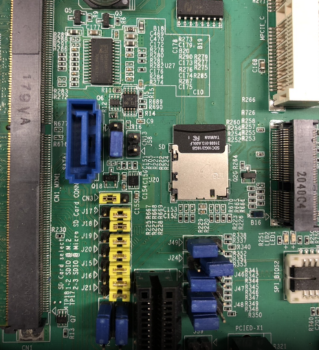
Step2: 將可開機的SD 卡插入底板SD卡卡槽(Plug the SD card into Carrier board 's SD card slot)
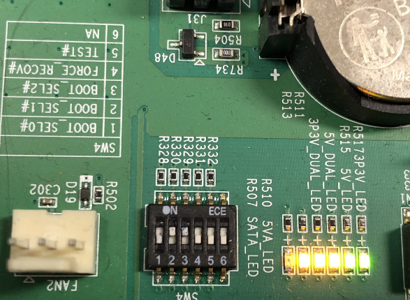
Step4: 確認開機選擇指撥開關
SD 卡開機模式: (2, 3:on, others off)
eMMC 開機模式: (1: on, others off)
Step3:打開電源 和 終端機 (Turn on the Power & Terminal)
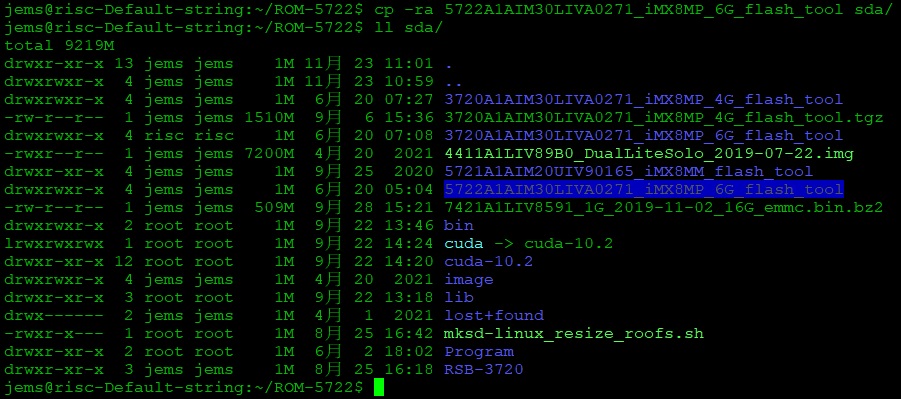
Step4: 解壓縮flash tools 檔案,並複製到U盤中(Unzip the flash tools file , then copy to USB Disk)
解壓縮(Unzip the file )
複製檔案到U盤中 (Copy the flash file to USB Disk)
1. 插入U盤到你的Ubuntu 電腦上 (Plug the USB Disk into you Linux PC
2. 檢視U盤在Ubuntu 系統代號 (Check the USB Disk's symbol in Ubuntu System)
3. 掛載U盤在Ubuntu 系統中 (Mount the USB Disk's in US)
4. 複製檔案到U盤(Copy the file to USB disk)
5. 將U盤連接到ROM-5722系統, 進入flsah tool下的mk_inand資歷夾, 執行指令./mksd-linux.sh /dev/mmcblk2燒錄image到eMMC(Connect USB Disk to ROM-5722 system, browser to mk_inand folder and execute flash shell script "./mksd-linux.sh /dev/mmcblk2"
| ROM-5722 | |
| SD card | /dev/mmcblk1 |
| eMMC | /dev/mmcblk2 |
6. 切換開機switch 1:on 2,3,4,5,6:off來設定成從eMMC開機(Change boot switch to "1:on 2,3,4,5,6:off" to boot from eMMC. Reboot system).
Debug 串口調試 (Debug port Setting)
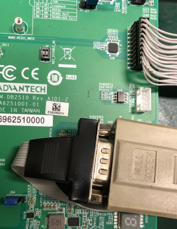
Debug port output:
| ROM-5722 CPU | ROM-5722 golden finger | DB5901 | DB2510 |
| UART1 | SER2 | CN15B down | COM3 |
| UART2: A53 | SER3 | COM3 | COM4 |
| UART3 | SER0 | CN15A up | COM1 |
| UART4: M7 | SER1 | COM1 | COM2 |
以 Tera Term 为例介绍如何使用串口调试功能
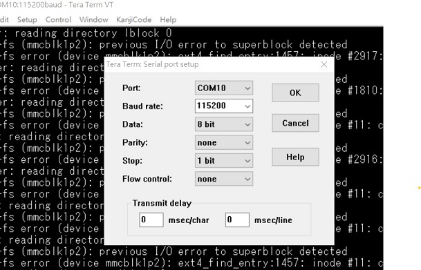
   Baud Rate波特率:115200
   Data 数据位:8
   Parity 奇偶校验:无
   Stop 停止位:1
   Flow Control流控:无
Tera Term Tool
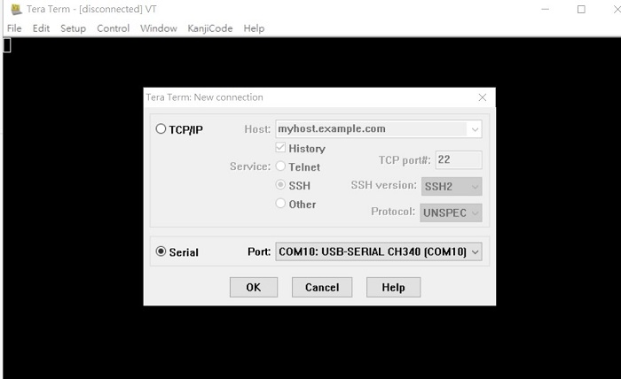
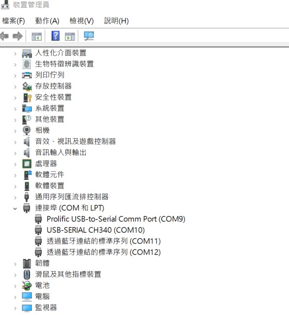
Check the Sriel port in Device Manager (查看PC端的串口号):
if you can not identify the Serial device , please check your serial driver.
Debug port connection (串口連接)
Log into Terminal Tool (进入串口调试终端):
Linux系统的基本使用(Linux System Basic Operating Method)
UUU 使用方法(USB Connection (OTG port))
Download uuu tool from (Release [ADVv20210429 · ADVANTECH-Corp/uuu · GitHub]) or in the folder.
uuu (Universal Update Utility) for nxp imx chips -- libuuu_1.3.191-67-ga9523ec
The “imx-boot-imx8mprom5722a1-6G.bin-flash_evk” file be included in 5722A1AIM30LIVA0XXX_iMX8MP_6G_misc.tgz. XXX is the version.
Connect USB cable to USB OTG port.
Change boot switch to "4:on 1,2,3,5,6:off" to boot from force recovery mode.
 Type command below to flash eMMC:
Display Setting (ROM-5722)
Ex:
setenv fdtfile imx8mp-rom5722-a1-lvds0-auo.dtb
U-boot Command :
- Display
- HDMI (default)
- imx8mp-rom5722-a1.dtb
- LVDS
- g070vw01(LVDS0) + HDMI
- imx8mp-rom5722-a1-lvds0-auo.dtb
- g070vw01(LVDS1) + HDMI
- imx8mp-rom5722-a1-lvds1-auo.dtb
- g215hvn01(DUAL LVDS) + HDMI
- imx8mp-rom5722-a1-lvds-dual.dtb
- g070vw01(LVDS0) + HDMI
- DSI
- adv7535(DSI to HDMI) + HDMI
- imx8mp-rom5722-a1-adv7535.dtb
- auog101uan02(DSI) + HDMI
- imx8mp-rom5722-a1-auog101uan02.dtb
- adv7535(DSI to HDMI) + HDMI
- HDMI (default)
- Camera
- OV5640 (default)
- imx8mp-rom5722-a1.dtb
- Basler camrea
- imx8mp-rom5722-a1-basler.dtb
- OV5640 (default)
乙太網路使用方法(Ethernent Testing Method)
Command : ifconfig
Command: Ping - I eth1 8.8.8.8 or Ping - I eth0 8.8.8.8
WiFi使用方法(WIFI Testing Method)
Command :
# killall wpa_supplicant
# ifconfig wlan0 up
# iwlist mlan0 scan
WEP:
# iwconfig mlan0 txpower auto essid "SSID" channel 4
# udhcpc -i mlan0

WPA/WPA2:
# wpa_passphrase "SSID" > wpa.conf
Type password
# wpa_supplicant -B -Dwext -imlan0 -c/home/root/wpa.conf
# udhcpc -i mlan0

ping 8.8.8.8
PING 8.8.8.8 (8.8.8.8) 56(84) bytes of data.
64 bytes from 8.8.8.8: icmp_seq=1 ttl=54 time=2.10 ms
64 bytes from 8.8.8.8: icmp_seq=2 ttl=54 time=2.10 ms
4G使用方法(4G Testing Method)
Command:
Test 4G: (EWM-C117FL06E - USB)
Step 1: Connect EWM-C117FL06E to Mini PCIE slot on 9680015491 and connect
the card to CN6 PCIe_D slot on ROM-DB5901.
Step 2: Connect the antenna 1750007990-01 to the SMA (F) connector on
9680015491
and connect the IPEX connector to MT1 on EWM-C117FL06E module.
Step 3: Connect the Mini USB cable from 9680015491 to USB 2.0 Type A port on
ROM-DB5901.
Step 4: Power on and execute the pppd command to connect to the network.
GPIO使用方法(GPIO Operating Method)
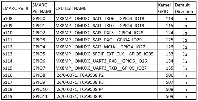
GPIO pin:
Loop-back Test (Take GPIO0 and GPIO2 as examples)

Step 1: Connect GPIO0 and GPIO2
Step 2: Export GPIO interface

root@imx8mprom5722a1: ~# echo 114 > /sys/class/gpio/export
root@imx8mprom5722a1: ~# echo 124 > /sys/class/gpio/export

Step 3: Set direction

root@imx8mprom5722a1: ~# echo out > /sys/class/gpio/gpio1/direction
root@imx8mprom5722a1: ~# echo in > /sys/class/gpio/gpio2/direction

Step 4: Read value and set output value then check

root@imx8mprom5722a1: ~# cat /sys/class/gpio/gpio2/value
0
root@imx8mprom5722a1: ~# echo 1 > /sys/class/gpio/gpio1/value
root@imx8mprom5722a1: ~# cat /sys/class/gpio/gpio2/value
1
串口使用方法(Serial Port Operating Method)
RS-232 Test
CN15上(SER0/UART3): /dev/ttymxc2
CN15 下(SER2/UART1): /dev/ttymxc0
COM 3 (A53 debug/SER3/UART2): /dev/ttymxc1
COM 1 (M7 debug/SER1/UART4): /dev/ttymxc3
SW7 Setting (SW7設置)
MODE1 MODE0
0 0 LOOPBACK
0 1 RS232
1 0 RS485
1 1 RS422
Loopback test (eg. ttymxc0)
Connect loopback test tool
- stty ‐F /dev/ttymxc0 115200
# stty ‐F /dev/ttymxc0 ‐echo
# cat /dev/ttymxc0 &
# echo test > /dev/ttymxc0
蓝牙使用方法(BlueTooth Operating Method)
Command :

$ hciconfig hci0 up
$ bluetoothctl
$ discoverable on
$ pairable on
$ scan on
[NEW] FC:18:3C:8D:75:F4 myphone
$ scan off
$ pair FC:18:3C:8D:75:F4
$ connect FC:18:3C:8D:75:F4
遠程訪問及文件傳輸(Remote Access and File Transimmion)
查看主板IP位址 ( Chech IP Address ):
Command : ifconfig
Windows下SSH访问及文件传输
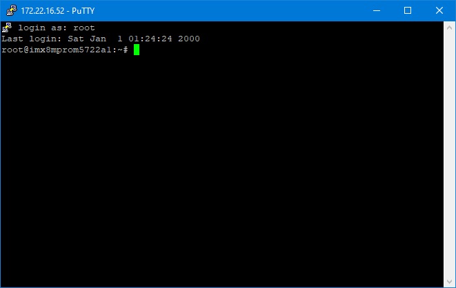
SSH Remote Log into Device
- SSH远程登录,以putty选择putty.exe(或者使用Xshell、SecureCRT等类似软件)
- 需要设置远程设备的IP、通讯端口(默认22)、通讯方式,登录后验证用户名密码
通用方法(General Method)
查看CPU温度(Check CPU Temperature)
    root@imx8mprom5722a1:/# cat /sys/devices/virtual/thermal/thermal_zone0/temp 44600

    # 或者直接以度爲單位顯示 echo $[$(cat /sys/class/thermal/thermal_zone0/temp)/1000]° >>> 45°
查看CPU频率(Check CPU Frequency)
           cat /sys/devices/system/cpu/cpu0/cpufreq/cpuinfo_cur_freq
           >> 900000
           cat /sys/devices/system/cpu/cpu0/cpufreq/cpuinfo_max_freq
           >> 1200000
查看内存容量(Check Memory Capacity)
root@imx8mprom5722a1:~# busybox free -m
              total        used        free      shared  buff/cache   available
Mem:        6002516      402812     5505276       26668       94428     5493888
Swap:             0           0           0
查看存储容量(Check Storage Capacity)
root@imx8mprom5722a1:~# busybox df -h
Filesystem                Size      Used Available Use% Mounted on
/dev/root                14.1G      3.6G      9.8G  27% /
devtmpfs                  2.4G      4.0K      2.4G   0% /dev
tmpfs                     2.9G         0      2.9G   0% /dev/shm
tmpfs                     2.9G     25.1M      2.8G   1% /run
tmpfs                     2.9G         0      2.9G   0% /sys/fs/cgroup
tmpfs                     2.9G         0      2.9G   0% /tmp
tmpfs                     2.9G    268.0K      2.9G   0% /var/volatile
/dev/mmcblk2p1           83.0M     29.6M     53.5M  36% /run/media/mmcblk2p1
tmpfs                   586.2M      4.0K    586.2M   0% /run/user/0
/dev/mmcblk1p1           83.0M     29.6M     53.5M  36% /run/media/mmcblk1p1
/dev/mmcblk1p2           14.2G      3.6G     10.0G  26% /run/media/mmcblk1p2
root@imx8mprom5722a1:~#
網路Ping測試(Ping Network Testing)
     ping 8.8.8.8
     PING 8.8.8.8 (8.8.8.8) 56(84) bytes of data.
     64 bytes from 8.8.8.8: icmp_seq=1 ttl=54 time=2.10 ms
     64 bytes from 8.8.8.8: icmp_seq=2 ttl=54 time=2.10 ms
設置RTC (RTC Setting)
root@imx8mprom5722a1:~# systemctl stop ntpdate.service
root@imx8mprom5722a1:~# date 090816072021 && hwclock -w && date
Wed Sep  8 16:07:00 UTC 2021
Tue Nov 23 07:38:50 UTC 2021
root@imx8mprom5722a1:~# date
Tue Nov 23 07:38:56 UTC 2021
root@imx8mprom5722a1:~#
Add Patch in linux-imx_6.1.bb file
SRC_URI:append:imx8qmrom5722a1 += " file://panel_gpi4.patch"
Linux BSP編譯方法(Linux BSP Compile Method)
Yocto 5.0
Yocto 4.2
Yocto 4.0
Yocto 3.0
============================================================================================================================================
Build known issue
如果有驗證上的錯誤 請使用以下的方法
### repo sync failed with Server certificate verification failed. CAfile: /etc/ssl/certs/ca-certificates.crt CRLfile: none ERROR: gstreamer1.0-1.14.4.imx-r0 do_unpack: Fetcher failure: Fetch command export PSEUDO_DISABLED=1; export PATH="/hom e/adv/adv-release-bsp/build_x11/tmp/work/aarch64-poky-linux/gstreamer1.0/1.14.4.imx-r0/recipe-sysroot-native/usr/bin/py thon3-native:/home/adv/adv-release-bsp/sources/poky/scripts:/home/adv/adv-release-bsp/build_x11/tmp/work/aarch64-poky-l inux/gstreamer1.0/1.14.4.imx-r0/recipe-sysroot-native/usr/bin/aarch64-poky-linux:/home/adv/adv-release-bsp/build_x11/tm p/work/aarch64-poky-linux/gstreamer1.0/1.14.4.imx-r0/recipe-sysroot/usr/bin/crossscripts:/home/adv/adv-release-bsp/buil d_x11/tmp/work/aarch64-poky-linux/gstreamer1.0/1.14.4.imx-r0/recipe-sysroot-native/usr/sbin:/home/adv/adv-release-bsp/b uild_x11/tmp/work/aarch64-poky-linux/gstreamer1.0/1.14.4.imx-r0/recipe-sysroot-native/usr/bin:/home/adv/adv-release-bsp /build_x11/tmp/work/aarch64-poky-linux/gstreamer1.0/1.14.4.imx-r0/recipe-sysroot-native/sbin:/home/adv/adv-release-bsp/ build_x11/tmp/work/aarch64-poky-linux/gstreamer1.0/1.14.4.imx-r0/recipe-sysroot-native/bin:/home/adv/adv-release-bsp/so urces/poky/bitbake/bin:/home/adv/adv-release-bsp/build_x11/tmp/hosttools"; export HOME="/home/adv"; git -c core.fsyncob jectfiles=0 submodule update --init --recursive failed with exit code 1, output:
Submodule 'common' (
https://anongit.freedesktop.org/git/gstreamer/common.git) registered for path 'common'
Cloning into '/home/adv/adv-release-bsp/build_x11/tmp/work/aarch64-poky-linux/gstreamer1.0/1.14.4.imx-r0/git/common'...
fatal: unable to access '
https://anongit.freedesktop.org/git/gstreamer/common.git/': server certificate verification fa iled. CAfile: /etc/ssl/certs/ca-certificates.crt CRLfile: none
fatal: clone of '
https://anongit.freedesktop.org/git/gstreamer/common.git' into submodule path '/home/adv/adv-release-b sp/build_x11/tmp/work/aarch64-poky-linux/gstreamer1.0/1.14.4.imx-r0/git/common' failed
Failed to clone 'common'. Retry scheduled
Cloning into '/home/adv/adv-release-bsp/build_x11/tmp/work/aarch64-poky-linux/gstreamer1.0/1.14.4.imx-r0/git/common'...
fatal: unable to access '
https://anongit.freedesktop.org/git/gstreamer/common.git/': server certificate verification fa iled. CAfile: /etc/ssl/certs/ca-certificates.crt CRLfile: none
fatal: clone of '
https://anongit.freedesktop.org/git/gstreamer/common.git' into submodule path '/home/adv/adv-release-b sp/build_x11/tmp/work/aarch64-poky-linux/gstreamer1.0/1.14.4.imx-r0/git/common' failed
Failed to clone 'common' a second time, aborting
ERROR: gstreamer1.0-1.14.4.imx-r0 do_unpack: Function failed: base_do_unpack
ERROR: Logfile of failure stored in: /home/adv/adv-release-bsp/build_x11/tmp/work/aarch64-poky-linux/gstreamer1.0/1.14. 4.imx-r0/temp/log.do_unpack.42631
ERROR: Task (/home/adv/adv-release-bsp/sources/meta-fsl-bsp-release/imx/meta-bsp/recipes-multimedia/gstreamer/gstreamer 1.0_1.14.imx.bb:do_unpack) failed with exit code '1'
ERROR: gstreamer1.0-plugins-base-1.14.4.imx-r0 do_unpack: Fetcher failure: Fetch command export PSEUDO_DISABLED=1; expo rt PATH="/home/adv/adv-release-bsp/build_x11/tmp/work/aarch64-mx8mm-poky-linux/gstreamer1.0-plugins-base/1.14.4.imx-r0/ recipe-sysroot-native/usr/bin/python3-native:/home/adv/adv-release-bsp/sources/poky/scripts:/home/adv/adv-release-bsp/b uild_x11/tmp/work/aarch64-mx8mm-poky-linux/gstreamer1.0-plugins-base/1.14.4.imx-r0/recipe-sysroot-native/usr/bin/aarch6 4-poky-linux:/home/adv/adv-release-bsp/build_x11/tmp/work/aarch64-mx8mm-poky-linux/gstreamer1.0-plugins-base/1.14.4.imx -r0/recipe-sysroot/usr/bin/crossscripts:/home/adv/adv-release-bsp/build_x11/tmp/work/aarch64-mx8mm-poky-linux/gstreamer 1.0-plugins-base/1.14.4.imx-r0/recipe-sysroot-native/usr/sbin:/home/adv/adv-release-bsp/build_x11/tmp/work/aarch64-mx8m m-poky-linux/gstreamer1.0-plugins-base/1.14.4.imx-r0/recipe-sysroot-native/usr/bin:/home/adv/adv-release-bsp/build_x11/ tmp/work/aarch64-mx8mm-poky-linux/gstreamer1.0-plugins-base/1.14.4.imx-r0/recipe-sysroot-native/sbin:/home/adv/adv-rele ase-bsp/build_x11/tmp/work/aarch64-mx8mm-poky-linux/gstreamer1.0-plugins-base/1.14.4.imx-r0/recipe-sysroot-native/bin:/ home/adv/adv-release-bsp/sources/poky/bitbake/bin:/home/adv/adv-release-bsp/build_x11/tmp/hosttools"; export HOME="/hom e/adv"; git -c core.fsyncobjectfiles=0 submodule update --init --recursive failed with exit code 1, output:
Submodule 'common' (
https://anongit.freedesktop.org/git/gstreamer/common.git) registered for path 'common'
Cloning into '/home/adv/adv-release-bsp/build_x11/tmp/work/aarch64-mx8mm-poky-linux/gstreamer1.0-plugins-base/1.14.4.im x-r0/git/common'...
fatal: unable to access '
https://anongit.freedesktop.org/git/gstreamer/common.git/': server certificate verification fa iled. CAfile: /etc/ssl/certs/ca-certificates.crt CRLfile: none
fatal: clone of '
https://anongit.freedesktop.org/git/gstreamer/common.git' into submodule path '/home/adv/adv-release-b sp/build_x11/tmp/work/aarch64-mx8mm-poky-linux/gstreamer1.0-plugins-base/1.14.4.imx-r0/git/common' failed
Failed to clone 'common'. Retry scheduled
Cloning into '/home/adv/adv-release-bsp/build_x11/tmp/work/aarch64-mx8mm-poky-linux/gstreamer1.0-plugins-base/1.14.4.im x-r0/git/common'...
fatal: unable to access '
https://anongit.freedesktop.org/git/gstreamer/common.git/': server certificate verification fa iled. CAfile: /etc/ssl/certs/ca-certificates.crt CRLfile: none
fatal: clone of '
https://anongit.freedesktop.org/git/gstreamer/common.git' into submodule path '/home/adv/adv-release-b sp/build_x11/tmp/work/aarch64-mx8mm-poky-linux/gstreamer1.0-plugins-base/1.14.4.imx-r0/git/common' failed
Failed to clone 'common' a second time, aborting
ERROR: gstreamer1.0-plugins-base-1.14.4.imx-r0 do_unpack: Function failed: base_do_unpack
ERROR: Logfile of failure stored in: /home/adv/adv-release-bsp/build_x11/tmp/work/aarch64-mx8mm-poky-linux/gstreamer1.0 -plugins-base/1.14.4.imx-r0/temp/log.do_unpack.51633
ERROR: Task (/home/adv/adv-release-bsp/sources/meta-fsl-bsp-release/imx/meta-bsp/recipes-multimedia/gstreamer/gstreamer 1.0-plugins-base_1.14.imx.bb:do_unpack) failed with exit code '1'
============================================================
nnshark error
https://community.nxp.com/t5/i-MX-Processors/Yocto-3-3-5-10-72-BSP-Build-Fail/m-p/1487902

