Difference between revisions of "DCIN701"
From ESS-WIKI
(Created page with " {{DISPLAYTITLE:ROM-2820 DCIN701}} ") |
|||
| Line 1: | Line 1: | ||
{{DISPLAYTITLE:ROM-2820 DCIN701}} | {{DISPLAYTITLE:ROM-2820 DCIN701}} | ||
| + | |||
| + | {| class="MsoTable15Plain2" style="width:425.2pt; border-collapse:collapse; border:solid #7f7f7f 1.0pt" width="567" | ||
| + | |- | ||
| + | | colspan="4" style="width:425.2pt; border-top:solid #7f7f7f 1.0pt; border-left:none; border-bottom:solid #7f7f7f 1.0pt; border-right:none; background:#cc00ff" width="567" | | ||
| + | '''<span lang="EN-US" style="color:white">DCIN1 (DC-Jack, +12v Power Input)</span>''' | ||
| + | |||
| + | |- | ||
| + | | style="width:42.5pt; border:none; border-bottom:solid #7f7f7f 1.0pt" width="57" | | ||
| + | Pin | ||
| + | |||
| + | | style="width:6.0cm; border:none; border-bottom:solid #7f7f7f 1.0pt" width="227" | | ||
| + | Signal | ||
| + | |||
| + | | style="width:42.5pt; border:none; border-bottom:solid #7f7f7f 1.0pt" width="57" | | ||
| + | Pin | ||
| + | |||
| + | | style="width:6.0cm; border:none; border-bottom:solid #7f7f7f 1.0pt" width="227" | | ||
| + | Signal | ||
| + | |||
| + | |- | ||
| + | | style="width:42.5pt; border:none; border-bottom:solid #7f7f7f 1.0pt" width="57" | | ||
| + | 1 | ||
| + | |||
| + | | style="width:6.0cm; border:none; border-bottom:solid #7f7f7f 1.0pt" width="227" | | ||
| + | +12V | ||
| + | |||
| + | | style="width:42.5pt; border:none; border-bottom:solid #7f7f7f 1.0pt" width="57" | | ||
| + | Shield | ||
| + | |||
| + | | style="width:6.0cm; border:none; border-bottom:solid #7f7f7f 1.0pt" width="227" | | ||
| + | GND | ||
| + | |||
| + | |} | ||
| + | |||
| + | [[File:ROM-2820 DCIN701.PNG]] | ||
| | ||
Latest revision as of 05:20, 28 June 2024
|
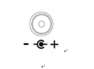
DCIN1 (DC-Jack, +12v Power Input) | |||
|
Pin |
Signal |
Pin |
Signal |
|
1 |
+12V |
Shield |
GND |
