Difference between revisions of "RSB-3720 user guide"
Jems.cheng (talk | contribs) |
Jems.cheng (talk | contribs) |
||
| Line 663: | Line 663: | ||
=== 設置LVDS clock (LVDS clock setting) === | === 設置LVDS clock (LVDS clock setting) === | ||
| − | + | ||
| + | <span style="font-size:small;"><span style="font-family:Arial,Helvetica,sans-serif;">Reference: </span></span> | ||
= <span style="font-size:small;"><span style="font-family:Arial,Helvetica,sans-serif;">[https://community.nxp.com/t5/i-MX-Processors/Limited-PLL-options-for-setting-up-LVDS-pixel-clock-on-IMX8MP/m-p/1502546#M193574 Limited PLL options for setting up LVDS pixel clock on IMX8MP]</span></span> = | = <span style="font-size:small;"><span style="font-family:Arial,Helvetica,sans-serif;">[https://community.nxp.com/t5/i-MX-Processors/Limited-PLL-options-for-setting-up-LVDS-pixel-clock-on-IMX8MP/m-p/1502546#M193574 Limited PLL options for setting up LVDS pixel clock on IMX8MP]</span></span> = | ||
Revision as of 06:26, 31 October 2023
Contents
- 1 資源特性(Features)
- 2 訂購資訊(Ordering Information)
- 3 規格(Specifications)
- 4 接口布局和尺寸(Layout and Sizes)
- 5 接口列表(Connector List)
- 6 快速入門 (Quick Start)
- 7 Linux 燒錄方法 (Linux Flash eMMC Method)
- 8 Linux系统的基本使用(Linux System Basic Operating Method)
- 8.1 Display Setting (RSB-3720)
- 8.2 乙太網路使用方法(Ethernent Testing Method)
- 8.3 WiFi使用方法(WIFI Testing Method)
- 8.4 4G使用方法(4G Testing Method)
- 8.5 GPIO使用方法(GPIO Operating Method)
- 8.6 LED_USER使用方法(LED_USER ON/OFF test)
- 8.7 COM1複合使用方法(COM1 complex Port Operating Method)
- 8.8 藍牙使用方法(BlueTooth Operating Method)
- 8.9 音訊使用方法(BlueTooth Operating Method)
- 8.10 I2C 測試( I2C Test method)
- 8.11 看門狗測試 (Watch Dog Test method)
- 8.12 攝像頭測試(Camera Test method)
- 8.13 遠程訪問及文件傳輸(Remote Access and File Transimmion)
- 9 通用方法(General Method)
- 10 Limited PLL options for setting up LVDS pixel clock on IMX8MP
資源特性(Features)
- NXP Arm® Cortex®-A53 i.MX8M Plus Quad/Dual up to 1.8 GHz
- Onboard LPDDR4 4 GB / 6 GB, 4000MT/s memory
- HDMI 1920x1080 at 60Hz, 1 Single or 1 Dual Channel 24 bit LVDS (or 1 4-Lane MIPI-DSI by BOM Option)
- 1 4-wire RS-232/422/485, 1 USB3.2 Gen1 By 1, 1 USB2.0, 1 Micro SD, 1 Mic. in / Line out
- 1 mini-PCIe for 3G/4G, 1 M.2 2230 Key E Slot
- Supports Yocto Linux and Android
- Support I/O Expansions boards by UIO40-Express
訂購資訊(Ordering Information)
規格(Specifications)
接口布局和尺寸(Layout and Sizes)
接口布局圖(Board Dimension Layout)
接口列表(Connector List)
| BAT | RTC Battery Connector |
| BL1 | LVDS Backlight 1 |
| BL2 | LVDS Backlight 2 |
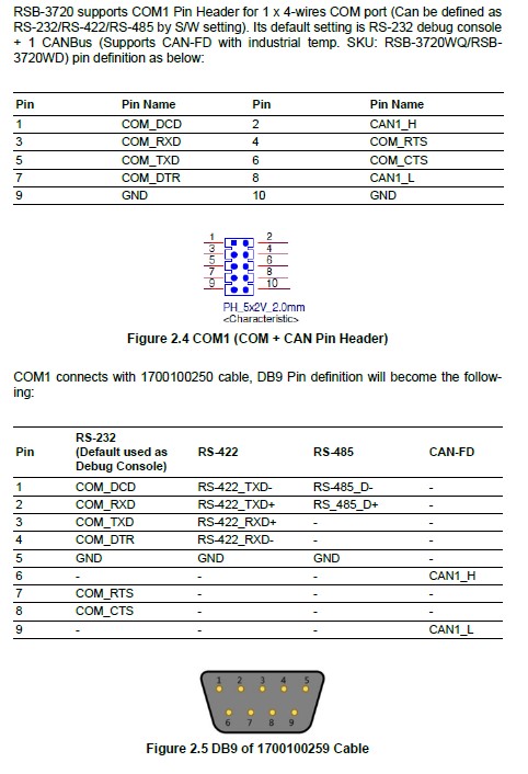
| COM1 | COM + CAN Pin Header (default as debug console) |
| CSI1 | MIPI-CSI Camera Input 1 |
| CSI2 | MIPI-CSI Camera Input 2 |
| DCIN/DCIN 1 | 12V DC Power Inout by DC Jack / by Pin Header |
| HDMI | HDMI CONN |
| LAN1 | Ethernet 1 |
| LAN2 | Ethernet 2 |
| LOUT | Line Out Pin Header |
| LVDS | LVDS CONN. |
| M2 | M.2 Key E CONN. |
| MIC | MIC In Pin Header |
| MPCIE | Mini-PCIe CONN. |
| RST | Rest Button |
| SD | SD Slot |
| UIO1 | UIO40-Express Pin Header 1 |
| UIO2 | UIO40-Express Pin Header 2 |
| USB1 | USB CONN. (USB 3.2 Gen 1 on TOP + USB 2.0 on BOT) |
接口引脚定義 (Pin definitions)
- BLP1
- BLP2
- VDD1
- SW1
- BAT (RTC Battery CONN.)
- BL1 (LVDS Backlight 1)
- BL2 (LVDS Backlight 2)
- COM1 (COM + CAN Pin Header): (default as debug console)
- CSI1 (MIPI-CSI Camera Input 1)
- CSI2 (MIPI-CSI Camera Input 2)
- DCIN/ DCIN1 (12V DC Power Input by DC Jack/ by Pin Header)
- HDMI (HDMI CONN.)
- LAN1 (Ethernet eth0)
- LAN2 (Ethernet eth1)
- LOUT (Line Out Pin Header)
- LVDS (LVDS CONN.)
- M2 (M.2 Key E CONN.)
- MIC (MIC In Pin Header)
- MPCIE (Mini-PCIe CONN.)
- RST (Reset Button)
- SD (SD Slot)
- SIM (SIM Slot)
- UIO1 (UIO40-Express Pin Header 1)
- UIO2 (UIO40-Express Pin Header 2)
- USB 1 (USB 3.2 Gen 1 on TOP + USB 2.0 on BOT)
- LED
機械尺寸(Mechanical Characteristics)
快速入門 (Quick Start)
系统下载 (OS Download)
Dropbox link for imx8 Yocto 3.0 BSP and Image
'Linux系统 (Linux OS)'
|
Git BSP Tag Version |
Product |
BSP/Image |
Date |
Alpha Release |
Beta Release |
MP Release |
Release Note |
Comment |
Release Owner |
| imx8LIVA0333.xml | RSB-3720 | 2021-10-05 |
Linux 燒錄方法 (Linux Flash eMMC Method)
1. 創建一個可以開機的SD Card (Create a bootable SD card )
先確認SD卡在Ubuntu 系統(x86) 所認到的SD卡代號 ( Check the SD card symbol in Ubuntu System (x86)
Command: sudo fdisk - l
2. 燒錄鏡像到SD 卡中. (Flash Image into SD card)
Command : sudo dd if=3720A1AIM30LIVA0333_iMX8MP_6G_2021-10-05.img of=/dev/sdf bs=1M conv=fsync
3. 將flash tool 拷貝到U盤 (Cpye the eMMC flash tool into USB Disk )
4. 設定終端機(Set Debug Terminal)
Debug 串口調試 (Debug port Setting)
以 Tera Term 為例介绍如何使用串口調試功能 ( Tera Term is kind of terminal tool , we need to set the parameter (Baud Rate , Data, Parity, Stop, Flow Control ) into "Tera Term terminal tool " )
   波特率(Baud Rate):115200
   數據位(Data):8
   奇偶校驗(Parity):无 (none)
   停止位(Stop):1
   流控(Flow Control):无 (none)
Tera Term Tool
Check the Sriel port in Device Manager (查看PC端的串口號):
if you can not identify the Serial device , please check your serial driver.
5. 將可開機的SD 卡插入 SD 插槽, 並打開電源開機 (Plug into the SD card into SD Card Slot , then turn on the power)
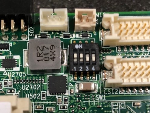
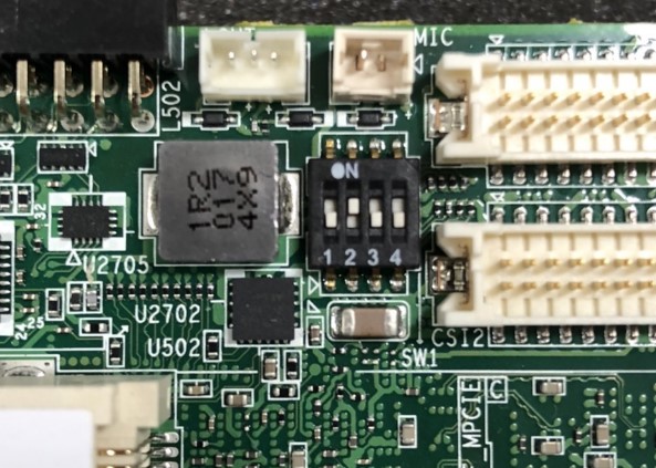
6. 確認撥碼開關 為 SD 卡開機模式 (Check the Switch)
SD 卡開機: 1, 2 on (Set the SD card boot up mode , 1 on 2 on )
'eMMC 開機: '2 on ( Set the eMMC boot up mode , 2 on , others off)
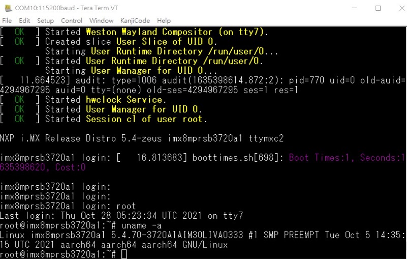
7.打開電源,由終端機可看到開機訊息 (Turn on the power , you will see the debug message from Terminal tool )
8. 開機後 請再重新開機一次,系統將會重新劃分磁區大小. (If you can not not copy the eMMC flash tool into root file system , please reboot the device , because , the system will the reconfigure the partition )
9. 燒錄eMMC前, 請將U盤插入USB port (Please pulg the USB Disk into USB port before flash eMMC)
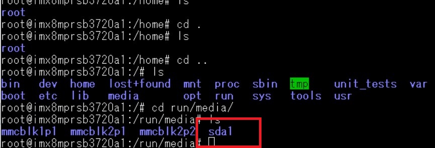
10. 在系統確認U盤 (Check the USB disk in the Yocto System (Device side) )
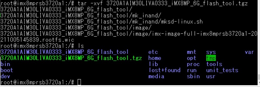
11. 將flash tool 燒錄鏡像,拷貝到根目錄 (Copy the flash tool into root file system)
12. 解壓縮 flash tool (Unzip the flash tool )
13. 執行燒錄eMMC (Exeucte the eMMC flash script )
Note: eMMC : /dev/mmcblk2
14. 移除SD卡 ,重新開機,並切換撥碼開關 (Remove the SD card , Change the Switch to eMMC mode , then reboot the system)
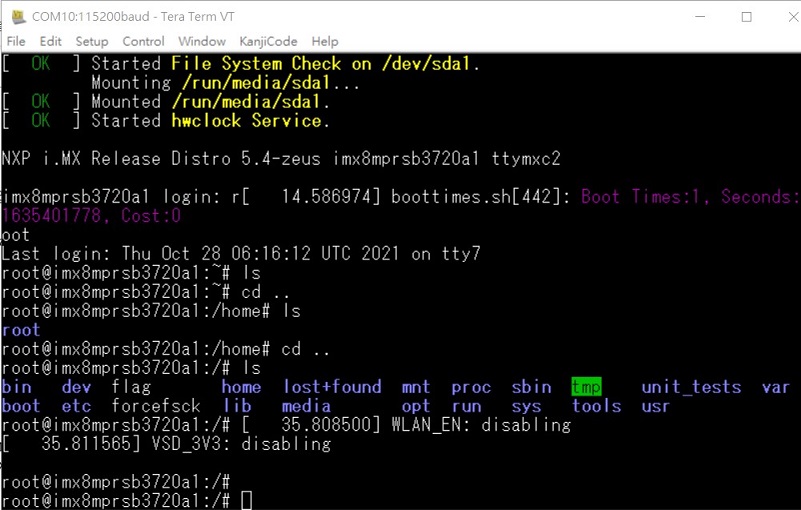
15. 從eMMC 開機,debug 訊息 (You will see the debug message when you boot up from eMMC flash )
Linux系统的基本使用(Linux System Basic Operating Method)
Display Setting (RSB-3720)
U-boot Command
- Display
- HDMI (default)
- imx8mp-rsb3720-a1.dtb
- LVDS
- g070vw01(LVDS0) + HDMI
- imx8mp-rsb3720-a1-lvds0-auo.dtb
- g070vw01(LVDS1) + HDMI
- imx8mp-rsb3720-a1-lvds1-auo.dtb
- g215hvn01(DUAL LVDS) + HDMI
- imx8mp-rsb3720-a1-lvds-dual.dtb
- g070vw01(LVDS0) + HDMI
- DSI
- adv7535(DSI to HDMI) + HDMI
- imx8mp-rsb3720-a1-adv7535.dtb
- auog101uan02(DSI) + HDMI
- imx8mp-rsb3720-a1-auog101uan02.dtb
- adv7535(DSI to HDMI) + HDMI
- HDMI (default)
- Camera
- OV5640 (default)
- imx8mp-rsb3720-a1.dtb
- Basler camrea
- imx8mp-rsb3720-a1-basler.dtb
- OV5640 (default)
乙太網路使用方法(Ethernent Testing Method)
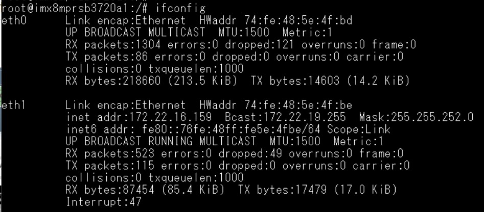
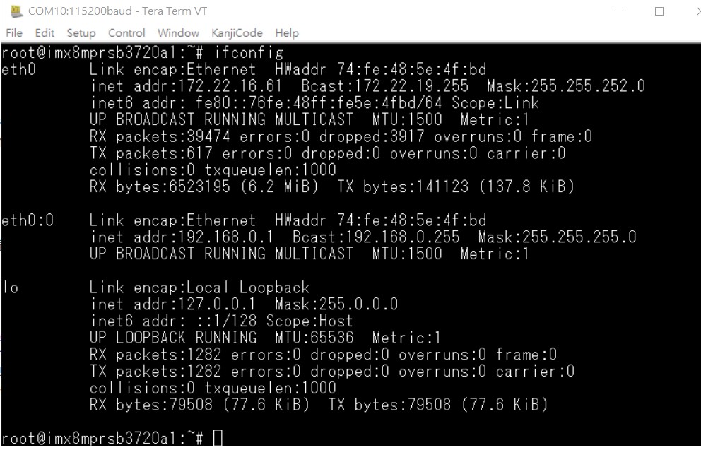
Command : ifconfig
Command: Ping 8.8.8.8
Change IP Addr Command:
Check Active Ethernet interface:
root@imx8mprsb3720a1:~# connmanctl services
*AR Wired ethernet_74fe485e4fbd_cable
Set static IP Addr:
- connmanctl config <service> --ipv4 manual <ip address> <netmask> <gateway>
# connmanctl config <service> --nameservers <dns-addr>
Example:
root@imx8mprsb3720a1:~# connmanctl config ethernet_74fe485e4fbd_cable --ipv4 manual 192.168.1.100 255.255.255.0 192.168.1.254
root@imx8mprsb3720a1:~# connmanctl config ethernet_74fe485e4fbd_cable --nameservers 8.8.8.8 4.4.4.4
WiFi使用方法(WIFI Testing Method)
# killall wpa_supplicant
# ifconfig wlan0 up
# wpa_passphrase "SSID" "PASSWORD" > /tmp/wpa.conf
# cat /tmp/wpa.conf
# wpa_supplicant -BDwext -iwlan0 -c/tmp/wpa.conf
# udhcpc -b -i wlan0
# ifconfig
# ping 8.8.8.8
Add DNS to /etc/resolv.conf
# cat /etc/resolv.conf
# Generated by Connection Manager
nameserver 8.8.8.8
nameserver 8.8.4.4
Now can ping google.com
# ping google.com
4G使用方法(4G Testing Method)
Check and change module to pppd mode
# stty -F /dev/ttyUSB3 –echo
# cat /dev/ttyUSB3 &
# echo AT+UUSBCONF? > /dev/ttyUSB3

Change to pppd mode:
# echo AT+UUSBCONF=0 > /dev/ttyUSB3

# echo AT+CFUN=16 > /dev/ttyUSB3
![]()
The module will be change to ttyACM0*, check again
# stty -F /dev/ttyACM0 –echo
# cat /dev/ttyACM0 &
# echo AT+UUSBCONF? > /dev/ttyACM0

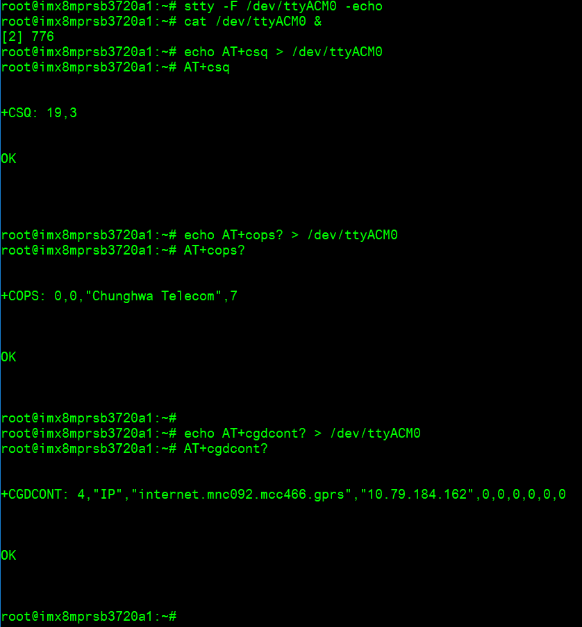
Set module to con
# stty -F /dev/ttyACM0 -echo
# cat /dev/ttyACM0 &
# echo AT+csq > /dev/ttyACM0
# echo AT+cops? > /dev/ttyACM0
# echo AT+cgdcont? > /dev/ttyACM0
Connect to Internet:
# pppd connect 'chat -v -s -t 10 "" "AT" "" "ATDT*99***4#" "CONNECT" ""' user username password password /dev/ttyACM2 460800 nodetach crtscts debug usepeerdns defaultroute &
# ifconfig

# ping 8.8.8.8
GPIO使用方法(GPIO Operating Method)
| GPIO Pin | Number |
| GPIO2 | 501 |
| GPIO4 | 503 |
| GPIO5 | 504 |
| GPIO6 | 505 |
| GPIO7 | 506 |
| GPIO8 | 507 |
| GPIO9 | 508 |
| GPIO10 | 509 |
| GPIO11 | 139 |
| GPIO12 | 138 |
Short GPIO pin 2 & pin 4
Short GPIO pin 5 & pin 6
Short GPIO pin 7 & pin 8
Short GPIO pin 9 & pin 10
Short GPIO pin 11 & pin 12
LED_USER使用方法(LED_USER ON/OFF test)
ON: echo 255 > /sys/class/leds/user/brightness
OFF: echo 0 > /sys/class/leds/user/brightness
COM1複合使用方法(COM1 complex Port Operating Method)
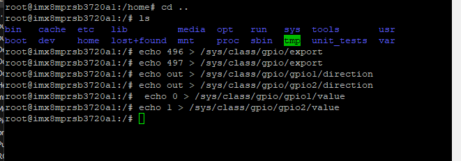
Note : please set the rs-485 , rs-422 GPIO setting with ssh console.
Set GPIO#496, #497
Set to 0,1 for RS-485
Set to 1,1 for RS-422
Set to 0,0 for loopback
Set to 1,0 for RS-232
RS-232 default as debug console)
RS-485 test
Test RS-485 with Adam-4520. Adam-4520 Pin to RSB-3720 COM1
Data- : Pin 1: COM_DCD
Data+ : Pin 3: COM_RXD

RS-485 test
# echo 496 > /sys/class/gpio/export
# echo 497 > /sys/class/gpio/export
# echo out > /sys/class/gpio/gpio1/direction
# echo out > /sys/class/gpio/gpio2/direction
# echo 0 > /sys/class/gpio/gpio1/value
# echo 1 > /sys/class/gpio/gpio2/value
# ./enable485 /dev/ttymxc2
# stty -F /dev/ttymxc2 speed 115200 ignbrk -brkint -icrnl -imaxbel -opost -onlcr -isig -icanon -iexten -echo -echoe -echok -echoctl -echoke
# cat /dev/ttymxc2 &
# echo "Serial Test" > /dev/ttymxc2
Will print “Serial Test” through RS-485
RS-232 -- Disable console
- Disable debug message output can also improve boot speed
Disable kernel message
setenv mmcargs setenv bootargs ${jh_clk} console=${console} modprobe.blacklist=${modprobe.blacklist} root=${mmcroot} video=HDMI-A-1:${videores} '''quiet'''
env save
reset
Or
Disable debug port
(1) Yocto machine setting:
modify /sources/meta-advantech/meta-fsl-imx/conf/machine$/${MC}.conf
SERIAL_CONSOLES = ";"
(2) Uboot parameter setting:
- For the imx8mq, imx8mm, imx8mp:
setenv console disabled
env save
reset
藍牙使用方法(BlueTooth Operating Method)
# hciattach /dev/ttymxc0 bcm43xx 115200 flow
# hciconfig hci0 up
# hcitool scan# bluetoothctl
# discoverable on
#pairable on
# scan on
# scan off
# pair 84:C5:A6:D3:AF:E4
# connect 84:C5:A6:D3:AF:E4
Check BT connect info
# info 84:C5:A6:D3:AF:E4
音訊使用方法(BlueTooth Operating Method)
Line-in , Line-out, MIC
1.Line-out
Command : gplay-1.0
2.MIC
Command : arecord
Check audio codec:

# cat /proc/asound/cards
 0 [sgtl5000       ]: sgtl5000 - sgtl5000
                      sgtl5000
 1 [audiohdmi      ]: audio-hdmi - audio-hdmi
                      audio-hdmi
root@imx8mprsb3720a1:~#
   Set Mic/audio volume
# amixer set Mic 100%
# amixer set Lineout 100%
# amixer set PCM 100%

Record and playback
Example command:
# arecord –t wav –c 1 –r 44100 –d 5 /tmp/mic.wav
# aplay /tmp/mic.wav

Record from MIC:
# arecord -D plughw:0,0 -r 16000 -f S16_LE ./f-16000.wav
Recording WAVE './f-16000.wav' : Signed 16 bit Little Endian, Rate 16000 Hz, Mono
# aplay f-16000.wav
Playing WAVE 'f-16000.wav' : Signed 16 bit Little Endian, Rate 16000 Hz, Mono

Play wav file from codec:
# aplay -D plughw:0,0 file_example_WAV_10MG.wav
Playing WAVE 'file_example_WAV_10MG.wav' : Signed 16 bit Little Endian, Rate 44100 Hz, Stereo

Play wav file from HDMI:
# aplay -D plughw:1,0 file_exam
ple_WAV_10MG.wav
Playing WAVE 'file_example_WAV_10MG.wav' : Signed 16 bit Little Endian, Rate 44100 Hz, Stereo
I2C 測試( I2C Test method)
Check I2C device (Audio codec: 0-000a)
# i2cdetect -y 0
I2C set and get:
# i2cset -f -y 0 0x0a 0 0xff00 w
# i2cget -f -y 0 0x0a 0 w
0x11a0
看門狗測試 (Watch Dog Test method)
System will reboot after 1 sec
# /unit_tests/Watchdog/wdt_driver_test.out 1 2 0
攝像頭測試(Camera Test method)
Check MIPI CSI camera
MIPI CSI0:
MIPI CSI1:

MIPI CSI0 - ov5640
Preview:
# gst-launch-1.0 v4l2src device=/dev/video0 ! video/x-raw,width=640,height=480 ! waylandsink
Capture:
# gst-launch-1.0 v4l2src num-buffers=1 device=/dev/video0 ! video/x-raw,width=640,height=480 ! jpegenc ! filesink location=sample.jpeg
MIPI CSI1 – ov5640
Preview:
# gst-launch-1.0 v4l2src device=/dev/video1 ! video/x-raw,width=640,height=480 ! waylandsink
Capture:
# gst-launch-1.0 v4l2src num-buffers=1 device=/dev/video1 ! video/x-raw,width=640,height=480 ! jpegenc ! filesink location=sample.jpeg
遠程訪問及文件傳輸(Remote Access and File Transimmion)
查看主板IP位址 ( check IP Address ):
Command : ifconfig
Windows下SSH訪問及文件傳輸
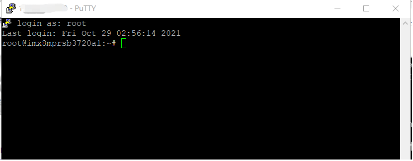
SSH Remote Log into Device
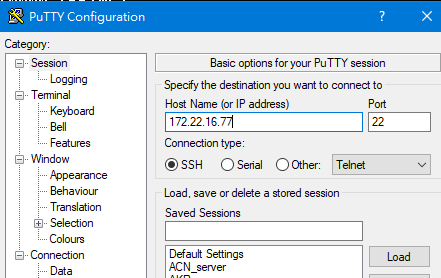
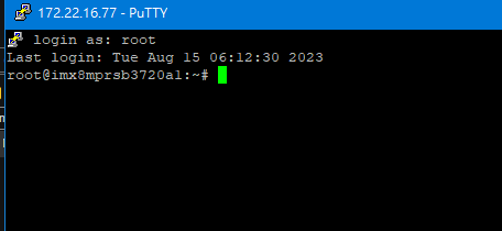
- SSH遠程登陸,以putty選擇putty.exe(或者使用Xshell、SecureCRT等類似軟件)
- 需要設置遠程設備的IP、通訊端口(默認22)、通訊方式錄后驗證用户名密碼
通用方法(General Method)
查看CPU温度(Check CPU Temperature)
    root@imx8mprsb3720a1:/# cat /sys/devices/virtual/thermal/thermal_zone0/temp   40000

    # 或者直接以度爲單位顯示 echo $[$(cat /sys/class/thermal/thermal_zone0/temp)/1000]° >>> 40°
查看CPU频率(Check CPU Frequency)
           cat /sys/devices/system/cpu/cpu0/cpufreq/cpuinfo_cur_freq
           >> 1200000
           cat /sys/devices/system/cpu/cpu0/cpufreq/cpuinfo_max_freq
           >> 1800000
查看内存容量(Check Memory Capacity)
root@imx8mprsb3720a1:/# busybox free -m
              total        used        free      shared  buff/cache   available
Mem:        6002524      393988     5517304       18460       91232     5507676
Swap:             0           0           0
查看存储容量(Check Storage Capacity)
root@imx8qxprom5620a1:/# busybox df -h
Filesystem                Size      Used Available Use% Mounted on
/dev/root                13.4G      1.7G     11.1G  13% /
devtmpfs                395.8M      4.0K    395.8M   0% /dev
tmpfs                   876.4M         0    876.4M   0% /dev/shm
tmpfs                   876.4M     16.5M    859.9M   2% /run
tmpfs                   876.4M         0    876.4M   0% /sys/fs/cgroup
tmpfs                   876.4M      4.0K    876.4M   0% /tmp
tmpfs                   876.4M    280.0K    876.2M   0% /var/volatile
/dev/mmcblk0p2           13.6G      1.7G     11.3G  13% /run/media/mmcblk0p2
/dev/mmcblk0p1           63.9M     23.4M     40.5M  37% /run/media/mmcblk0p1
/dev/mmcblk1p1           63.9M     23.4M     40.5M  37% /run/media/mmcblk1p1
tmpfs                   175.3M     88.0K    175.2M   0% /run/user/0
root@imx8qxprom5620a1:/#
網路Ping測試(Ping Network Testing)
     ping 8.8.8.8
     PING 8.8.8.8 (8.8.8.8) 56(84) bytes of data.
     64 bytes from 8.8.8.8: icmp_seq=1 ttl=54 time=2.10 ms
     64 bytes from 8.8.8.8: icmp_seq=2 ttl=54 time=2.10 ms
設置RTC (RTC Setting)
Disable RTC sync service
# systemctl disable ntpd.service
![]()
# systemctl stop systemd-timesyncd
# systemctl stop ntpdate.service
![]()
Set system time to current, then write to RTC
# date 040710522021 && hwclock -w && date

Set incorrect time, then read time from RTC
# date 010100002000 && hwclock -r && date

Restart the RTC time to system time
# hwclock -s && date
設置LVDS clock (LVDS clock setting)
Reference:
Limited PLL options for setting up LVDS pixel clock on IMX8MP
Linux BSP編譯方法(Linux BSP Compile Method)
Yocto 4.0
Yocto 3.3
Yocto 3.0
如果有驗證上的錯誤 請使用以下的方法 (if you have the build error , please use " git config --global http.sslverify false"
### repo sync failed with Server certificate verification failed. CAfile: /etc/ssl/certs/ca-certificates.crt CRLfile: none
============================================================
export GIT_SSL_NO_VERIFY=1
#or
git config --global http.sslverify false
============================================================
Add git and vim into image:
Add below in "conf/local.conf" file:
IMAGE_INSTALL_append = " git-perltools vim "
For install vim in xwayland, please add below into "meta/recipes-support/vim/vim_8.1.1518.bb b/meta/recipes-support/vim/vim_8.1.1518.bb" fie:
PACKAGECONFIG_remove = " x11 "


