Difference between revisions of "Windows IoT Enterprise RSB-3720"
Jems.cheng (talk | contribs) (→UART:) |
Jems.cheng (talk | contribs) |
||
| Line 191: | Line 191: | ||
| − | |||
| − | |||
| − | |||
| − | |||
| − | |||
| − | |||
| − | |||
| − | |||
| − | |||
| − | |||
| − | |||
| − | |||
| − | |||
| − | |||
| − | |||
| − | |||
| − | |||
| − | |||
| − | |||
| − | |||
| − | |||
| − | |||
| − | |||
| − | |||
| − | |||
| − | |||
| − | |||
| − | |||
| − | |||
| − | |||
| − | |||
| − | |||
| − | |||
| − | |||
| − | |||
| + | | ||
== I2C: == | == I2C: == | ||
Revision as of 06:41, 21 October 2024
Contents
Get Started with Windows 10 IoT Version 1.3.0 Enterprise Using the Advantech RSB-3720, an Arm-based 2.5” Pico-ITX with NXP i.MX 8M Plus
1.Introdouction
Advantech has updated its board support packages (BSP) to version 1.3.0, based on i.MX Windows 10 IoT released by NXP. These updates have been installed on the RSB-3720, featuring i.MX 8M Plus series processor platforms to support Windows 10 IoT Enterprise Version 1.3.0.
This how-to article describes the process of building and installing Windows 10 IoT BSP Version 1.3.0 on the Advantech RSB-3720. The highly optimized Windows 10 IoT BSP simplifies the setup installation with only one SD card, making it as easy as installing Windows OS on X86.
Additionally, Version 1.3.0 includes all the necessary code, documents, and tools to help users build and run Windows 10 IoT on the i.MX 8M Plus from scratch. Check our release notes for a full review of the capabilities of Windows 10 on Arm of the i.MX 8M Plus processor.
2. Prerequisites
- The Advantech RSB-3720 — a 2.5” Pico-ITX SBC with NXP i.MX8M Plus SOC
- 1 x 8GB Micro SD card for flashing the OS installer
- 1 x micro USB cable for flashing the boot loader
- 1 x power adapter (input: 100 ~ 240V AC 50/60Hz; output: DC 12V 3A; Advantech P/N: 96PSA-A36W12R1-3)
Necessary Software:
- Win32 Disk Imager
Please follow the link below to download an executable file.
3. Install Windows 10 IoT Enterprise on RSB-3720
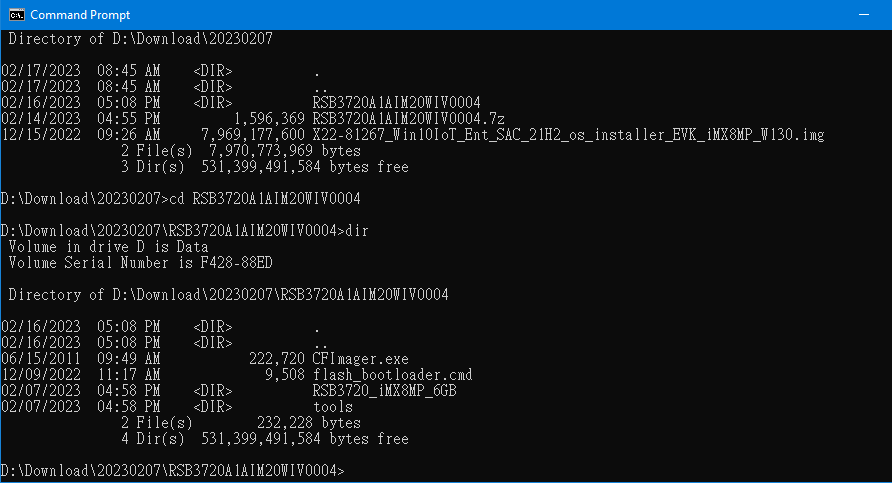
3-1. Extract the zip file (file name: 20230207.zip) of the image package you downloaded.
3-2. Extract the zip file (RSB3720A1AIM20WIV0004.7z) in the folder and flash the firmware into eMMC
3-3. Prepare one 8GB SD card for flashing OS installer in your host PC whether it is Linux or Windows operating system.
A. For the Linux operating system:
$ sudo dd if=X22-81267_Win10IoT_Ent_SAC_21H2_os_installer_EVK_iMX8MP_W130.img of=/dev/sdX bs=1M conv=fsync
B. For the Windows operating system:
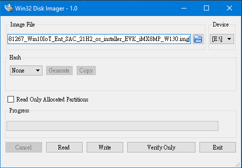
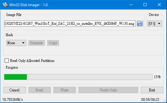
Use the Win32 Disk Imager to prepare the 1 x 8GB Mirco SD card used for flashing the OS installer
with the Windows-based Host PC.
Start the OS installer process.
Finish the OS installer process and close the Win32 Disk Imager tool.
3-4. Flash firmware image into the same Micro SD card
A. Open the “CMD” in the Windows OS, then enter RSB3720A1AIM20WIV0004.
B. Next, flash the firmware image onto a Micro SD card by command. Please check your micro SD card symbol.
For example: the Mirco SD card is “g:” in your windows system.
Command:
flash_bootloader.cmd /device RSB3720_iMX8MP_6GB /target_drive g:
3-5. Flash Windows IoT to eMMC
A. Set up the SW1 jumper on the RSB-3720 for SD boot. (ON-ON-OFF-OFF).
B. Connect the HDMI cable on the device.
C. Insert a micro SD card and power the device on. The system will first start a PE environment for installation.
Next, the system will reboot again and enter the setup process.
A Window 10 IoT enterprise desktop will appear on the screen after the settings are complete.
[Notice]
A. Make sure to disable sleep in “Power and sleep” settings after Windows OS boots up
to avoid unexpected system hangs.
B. Never remove the SD card upon boot up:
The SD card shouldn’t be removed when Window 10 IoT enterprise is loading as there is no OTG port on the RSB-3720 to flash load firmware onto the eMMC mentioned in the step of flashing firmware image into the same Micro SD card.
C. After the RSB-3720 is successfully boot into the Windows 10 IoT enterprise, you can use this same SD card to flash another RSB-3720 to Windows 10 IoT enterprise if you want. But before doing so, please reset the SD card to its initial status by the following method before you unplug the SD card and plug into a new RSB-3720. Please follow the steps below to initialize the SD card:
i. Rename the “_efi” folder to “EFI”
ii. Change partition id. using a Windows command line
<code> C:\Windows\system32> diskpart

DISKPART> list disk
Disk ###  Status         Size     Free     Dyn  Gpt
--------  -------------  -------  -------  ---  ---
Disk 0    Online          465 GB  1024 KB        *
Disk 1    No Media           0 B      0 B
Disk 2    Online           14 GB      0 B        *

DISKPART> sel disk 2
Disk 2 is now the selected disk.
DISKPART> list partition

Partition ###  Type              Size     Offset
-------------  ----------------  -------  -------
Partition 1    Unknown             32 MB  1024 KB
Partition 2    Primary             29 GB    33 MB

DISKPART> sel partition 1
Partition 1 is now the selected partition.
DISKPART> set id="c12a7328-f81f-11d2-ba4b-00a0c93ec93b"
DiskPart successfully set the partition ID.
DISKPART> exit</code>
4. Conclusion
Version 1.3.0 significantly reduces the installation process, taking only about 30 minutes. So, grab a cup of coffee while you wait. More native functions are now enabled, such as dual LANs and native HDMI. You can experience its out-of-the-box capabilities and meet your development needs.
Test method:
RTC:
測試方法 :
1. In Windows
- 離線測試
- 接上網路測試
- 調整 12 /24 小時制
2. 在 U EFI S hell
- 開機時一直按 ESC ,會出現 U EFI 選單,選擇 Boot Manager ””→ UEFI Shell
- 輸入指令
I2C:
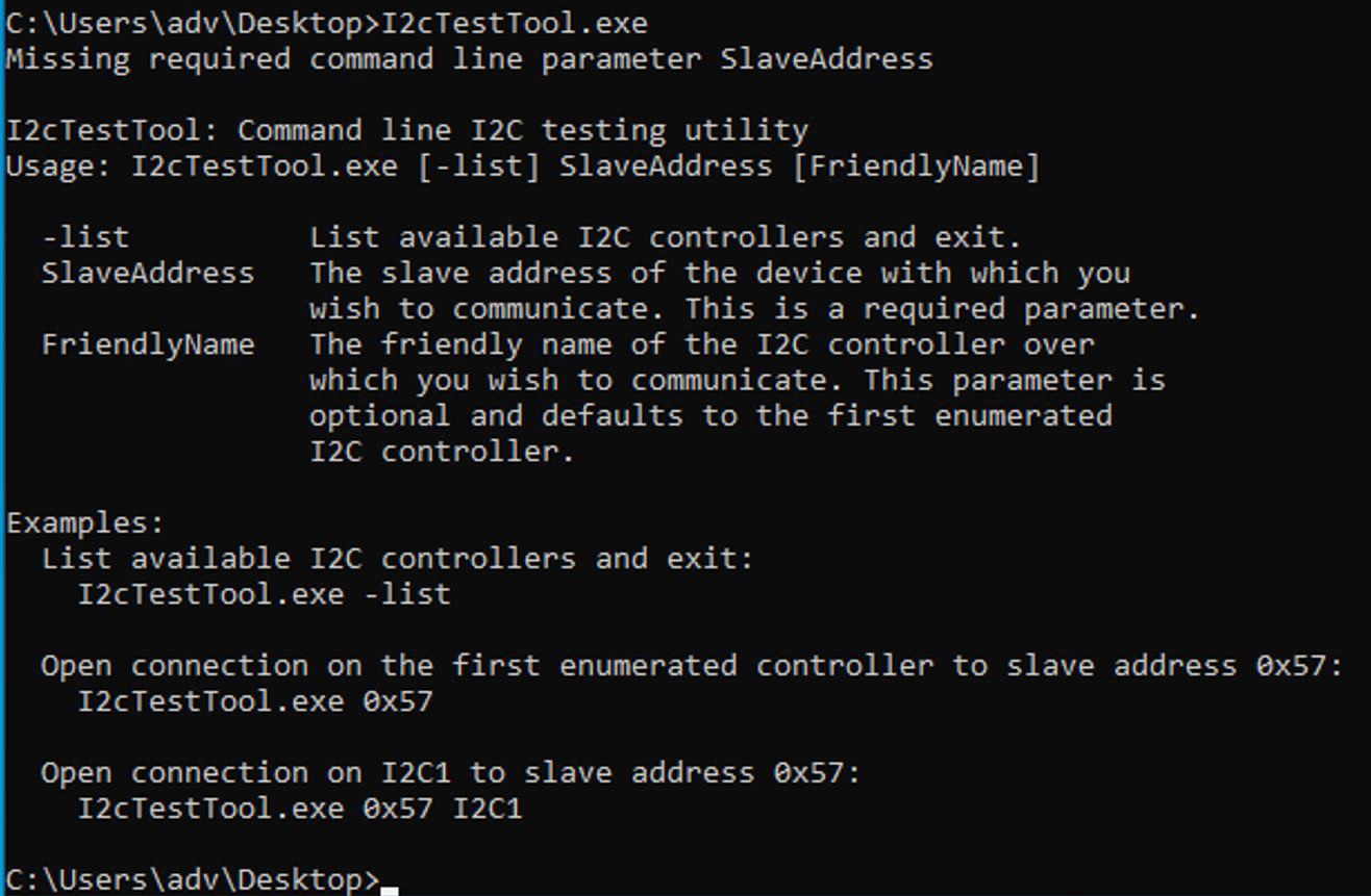
測試工具:I2cTestTool.exe
測試指令:
#列出使用方式
- 列出所有 I 2C c ontroller
> I2cTestTool.exe list
- 讀取某個 b us 上的 s lave address 裝置 底下是讀取 S TGL5000 s lave address 0xa 長度為 10的值
> I2cTestTool.exe 0 x0a I2C1
> r ead 10
CANBus:
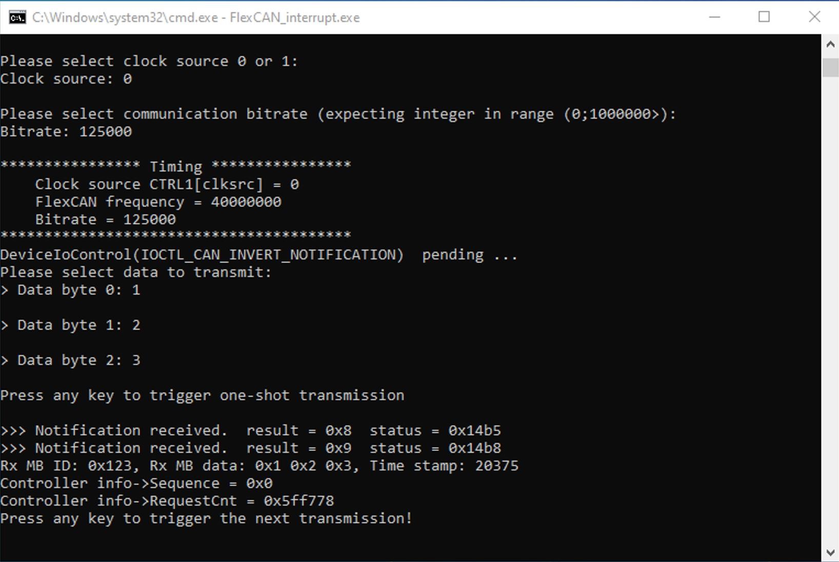
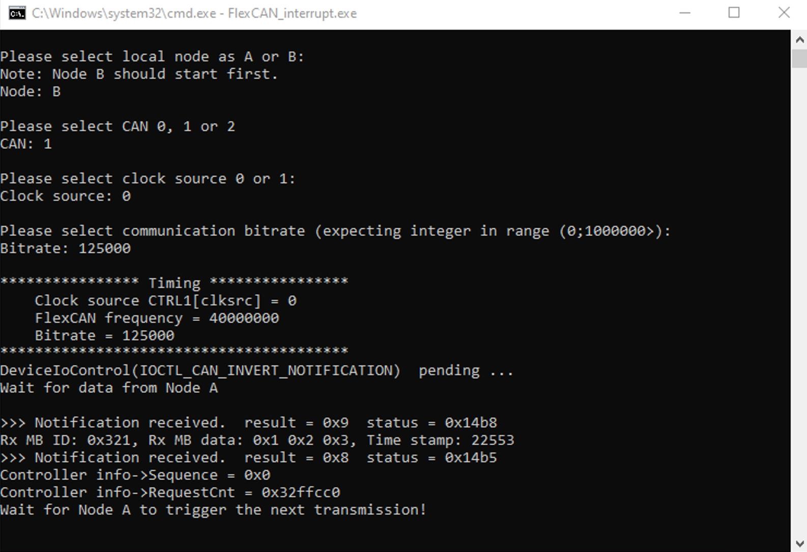
測試工具:FlexCAN_interrupt.exe
測試接法:使用 UIO 4034 + 平行線 + 一對二 (CAN/Debug)
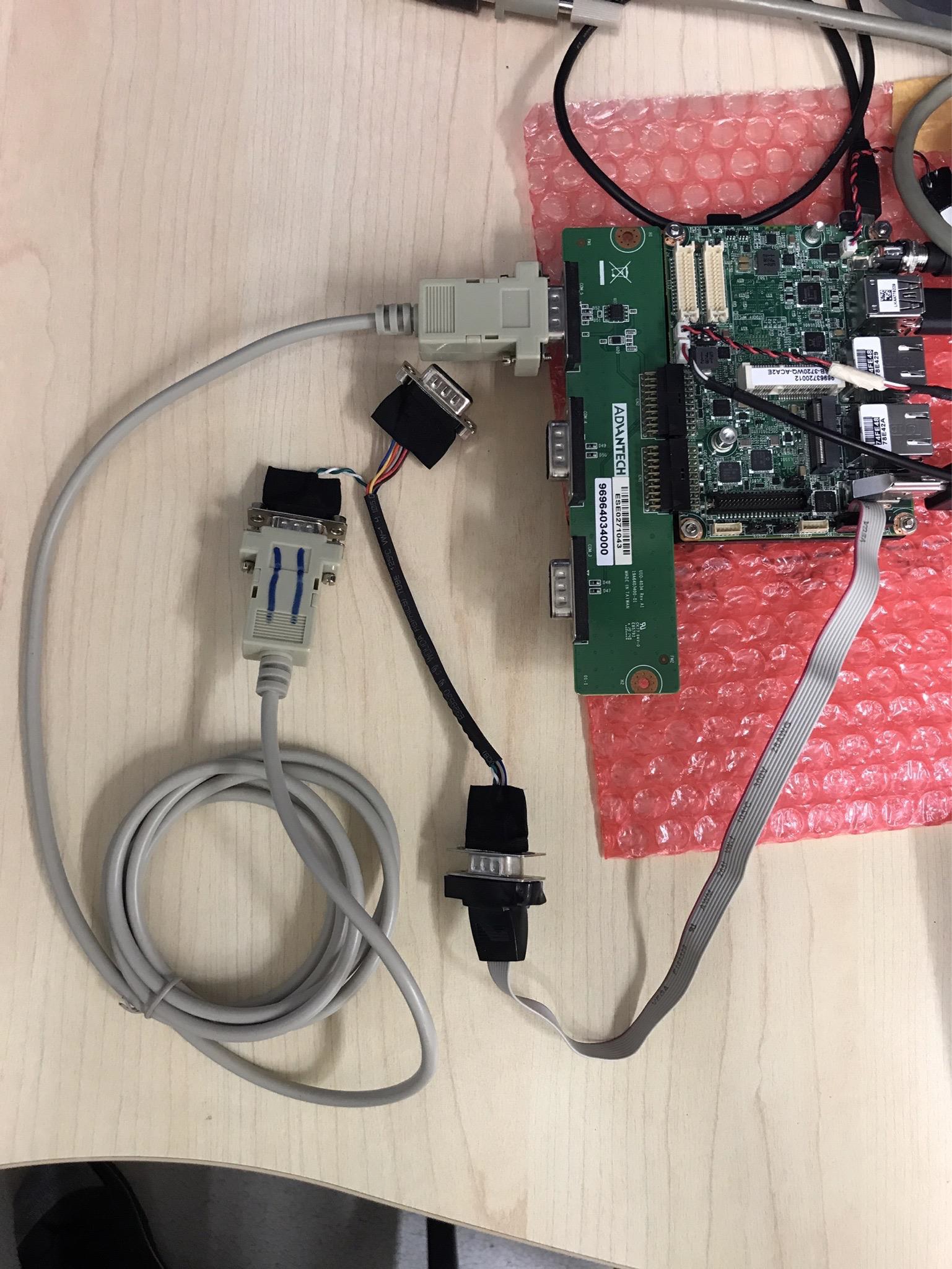
開啟兩個命令提示字元 視窗,依據畫面輸入測試指令,假設拔掉 cable ,,”Press any key to trigger
the next transmission” 便無法執行,直到接上 cable 會吐出結果


