显示接口(LVDS,LVDS Balight,HDMI)
Contents
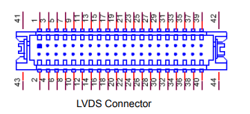
LVDS Connector (CN4)
RSB-4680 provides a LVDS 20x2-pin board-to-board connector for dual channel 18/ 24/30 bit LVDS panel up to 1920 x 1080. For avoid to damage to the LCD panel, please make sure to set the right voltage level before powering on while connecting a LVDS panel (refer to jumper setting description for LVDS_BLP, LVDS_VDD1 and LVDS_VDD2 and LCD datasheet that you will use).
| Pin | Pin Name | Pin | Pin Name |
| 1 | +VDD_LVDS |
2 | +VDD_LVDS |
| 3 | GND | 4 | GND |
| 5 | +VDD_LVDS |
6 | +VDD_LVDS |
| 7 | LVDS0_D0- |
8 | LVDS1_D0- |
| 9 | LVDS0_D0+ |
10 | LVDS1_D0+ |
| 11 | GND | 12 | GND |
| 13 | LVDS0_D1- |
14 | LVDS1_D1- |
| 15 | LVDS0_D1+ |
16 | LVDS1_D1+ |
| 17 | GND | 18 | GND |
| 19 | LVDS0_D2- |
20 | LVDS1_D2- |
| 21 | LVDS0_D2+ |
22 | LVDS1_D2+ |
| 23 | GND | 24 | GND |
| 25 | LVDS0_CLK- |
26 | LVDS1_CLK- |
| 27 | LVDS0_CLK+ |
28 | LVDS1_CLK+ |
| 29 | GND | 30 | GND |
| 31 | LVDS0_D3- |
32 | LVDS1_D3- |
| 33 | LVDS0_D3+ |
34 | LVDS1_D3+ |
| 35 | LVDS_DDC_DAT |
36 | LVDS_DDC_CLK |
| 37 | LVDS0_D4- |
38 | LVDS1_D4- |
| 39 | LVDS0_D4+ |
40 | LVDS1_D4+ |
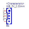
LVDS Backlight Connector (LVDS_BL)
For avoiding to damage LCD panel, please make sure set a right voltage level before power on while connecting a LVDS panel (refer to jumper setting description for LVDS_BLP and LCD datasheet that you will use).
| Pin | Pin Name |
| 1 | +VDD_BKLT_LVDS |
| 2 | GND |
| 3 | LVDS_BKLT_EN |
| 4 | LVDS_BKLT_PWM |
| 5 | VCC_SYS(+5V) |
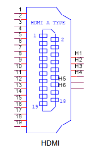
HDMI Display Interface (HDMI)
RSB-4680 provides one HDMI interface connector. HDMI technology can support a maximum resolution of 3840 x 2160, but the actual resolution supported depends on the monitor being used.
| Pin | Description | Pin | Description |
| 1 | HDMI _D2+ |
11 | GND |
| 2 | GND | 12 | HDMI _CLK- |
| 3 | HDMI _D2- |
13 | HDMI_CEC |
| 4 | HDMI_ D1+ |
14 | NC |
| 5 | GND | 15 | HDMI _CTRL_CLK |
| 6 | HDMI _D1- |
16 | HDMI _CTRL_DAT |
| 7 | HDMI _D1+ |
17 | GND |
| 8 | GND | 18 | +5V_HDMI_2 |
| 9 | HDMI _D0- |
19 | HDMI _HPD |
| 10 | HDMI_CLK+ |
|
|
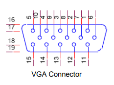
VGA Display Interface (VGA)
RSB-4680 provides standard VGA connector. VGA resolution supports up to 1920x1200.
| Pin | Description | Pin | Description |
| 1 | RED |
9 | +5V_CRT |
| 2 | GREEN |
10 | GND |
| 3 | BLUE |
11 | N/A |
| 4 | N/A |
12 | DDC_DATA |
| 5 | GND |
13 | HSYNC |
| 6 | GND |
14 | VSYNC |
| 7 | GND |
15 | DDC_CLK |
| 8 | GND |
|
|


