Step 1: First change ROM-ED91 SW1201 to ‘11’.
Step 2: Test RS-422 with Adam-4520. Connect Adam-4520 with COMA with DB9 as the following:
# stty -F /dev/ttyLP0 speed 115200 ignbrk -brkint -icrnl -imaxbel -opost -onlcr -isig -icanon -iexten -echo -echoe -echok -echoctl -echoke
# cat /dev/ttyLP0 &
# echo "Serial Test" > /dev/ttyLP0
Step 1: First change ROM-ED91 SW1201 to ‘10’.
Step 2: Test RS-485 with Adam-4520. Connect Adam-4520 with COMA with DB9 as the following:
# stty -F /dev/ttyLP0 speed 115200 ignbrk -brkint -icrnl -imaxbel -opost -onlcr -isig -icanon -iexten -echo -echoe -echok -echoctl -echoke
# cat /dev/ttyLP0 &
# echo "Serial Test" > /dev/ttyLP0
GPIO Loopback Test (Using GPIO1 and GPIO2 as examples)
Step 1: Connect GPIO1 and GPIO2
Step 2: Export GPIO interface
# echo 416 > /sys/class/gpio/export
# echo 417 > /sys/class/gpio/export
Step 3: Set GPIO direction
# echo out > /sys/class/gpio/gpio1/direction
# echo in > /sys/class/gpio/gpio2/direction
Step 4: Read value and set output value than check
# cat /sys/class/gpio/gpio2/value 0
# echo 1 > /sys/class/gpio/gpio1/value
# cat /sys/class/gpio/gpio2/value
1
=== Camera使用方法(Camera Testing Method) ===
MIPI-CSI0 (Tested with OV5640 + mini-SAS to MIPI-CSI Cable): OV5640 CSI (CN701): Connect OV5640 camera to EG-55 CAM3
Step 1: Take pictures
# gst-launch-1.0 v4l2src num-buffers=1 device=/dev/video0 ! video/x-raw,width=640,height=480 ! jpegenc ! filesink location=sample.jpeg
Step 2: View on panel
# gplay-1.0 sample.jpeg
PWM測試方法(PWM Testing Method)
Please use oscilloscope to check waveform.
PWM1:
# echo 4 > /sys/class/pwm/pwmchip0/export
# echo 1000000 > /sys/class/pwm/pwmchip0/pwm4/period
# echo 500000 > /sys/class/pwm/pwmchip0/pwm4/duty_cycle
# echo 1 > /sys/class/pwm/pwmchip0/pwm4/enable
PWM2:
# echo 5 > /sys/class/pwm/pwmchip6/export
# echo 1000000 > /sys/class/pwm/pwmchip6/pwm5/period
# echo 500000 > /sys/class/pwm/pwmchip6/pwm5/duty_cycle
# echo 1 > /sys/class/pwm/pwmchip6/pwm5/enable
PWM3:
# echo 2 > /sys/class/pwm/pwmchip6/export
# echo 1000000 > /sys/class/pwm/pwmchip6/pwm2/period
# echo 500000 > /sys/class/pwm/pwmchip6/pwm2/duty_cycle
# echo 1 > /sys/class/pwm/pwmchip6/pwm2/enable
PWM4:
# echo 3 > /sys/class/pwm/pwmchip6/export
# echo 1000000 > /sys/class/pwm/pwmchip6/pwm3/period
# echo 500000 > /sys/class/pwm/pwmchip6/pwm3/duty_cycle
# echo 1 > /sys/class/pwm/pwmchip6/pwm3/enable
PWM5:
# echo 4 > /sys/class/pwm/pwmchip6/export
# echo 1000000 > /sys/class/pwm/pwmchip6/pwm4/period
# echo 500000 > /sys/class/pwm/pwmchip6/pwm4/duty_cycle
# echo 1 > /sys/class/pwm/pwmchip6/pwm4/enable
M33 Function
We use default M-core firmware to verify each of IO feature. User should connect COME_DEBUG port to PC and there were show screen as demonstration below:
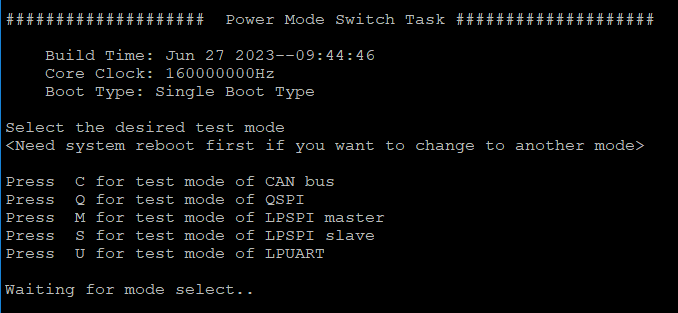
Press C for test mode of CAN bus
Press Q for test mode of QSPI
Press M for test mode of LPSPI master
Press S for test mode of LPSPI slave
Press U for test mode of LPUART
About this firmware, user should note that if you want to switch to another test mode, you must reboot the system.
CAN Bus
Step 1: Prepare two pcs rom-2620. One for ‘Node A’ one for ‘Node B’
Step 2: Connect these two boards (HI-HI/LO-LO)
Step 3: The test steps and screen are as below :
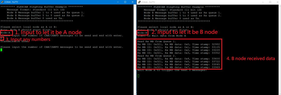
Step 4: Follow the figure (step1 - step4). If B node received data means test successful.
QSPI
Step 1: After select the test mode ‘Q’ to verify QSPI, you will see below screen.
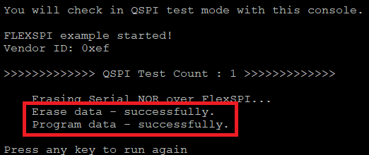
Step 2: This test program will perform QSPI erase/write automatically and show ‘successfully’ when it’s done.
Step 3: User can press any key to run again.
LPSPI
Step 1: Two pcs rom-2620. One for ‘Master’ one for ‘Slave’.
Step 2: Connection with these two boards by SPI Bus as below:
LPSPI3_PCS0 -- LPSPI3_PCS0
LPSPI3_GND -- LPSPI3_GND
LPSPI3_PCS1 -- LPSPI3_PCS1
LPSPI3_SCK -- LPSPI3_SCK
LPSPI3_SOUT -- LPSPI3_SIN
LPSPI3_SIN -- LPSPI3_SOUT
Step 3: One board select mode ‘M’ to be Master.
Step 4: The second board is specified to Slave by select mode ‘S’.
Step 5: The test screen as below:
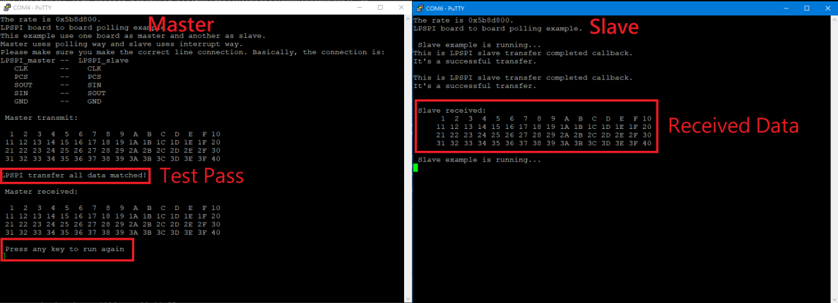
Step 6: Press any key at terminal of node master, it will execute the test again.
LPUART
Step 1: Change ROM-ED91 SW1203 to '01'.
Step 2: Connect COM-B and COM-E to PC.
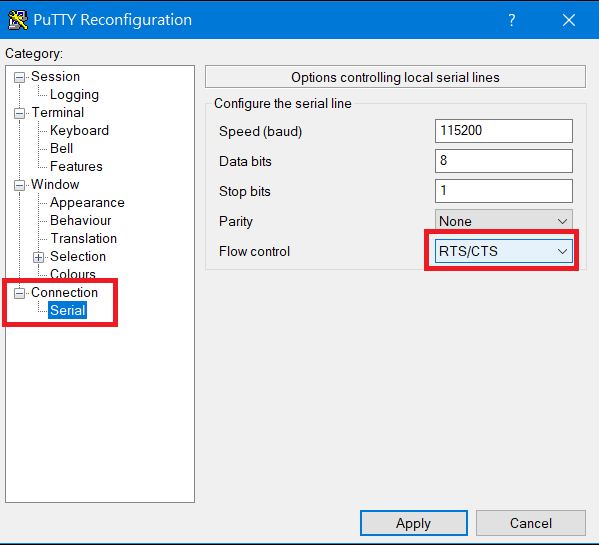
Step 3: Set RTS/CTS flow control for COM-B in Putty.exe
Step 4: After select the test mode ‘U’ to verify LPUART2, you will see below screen.
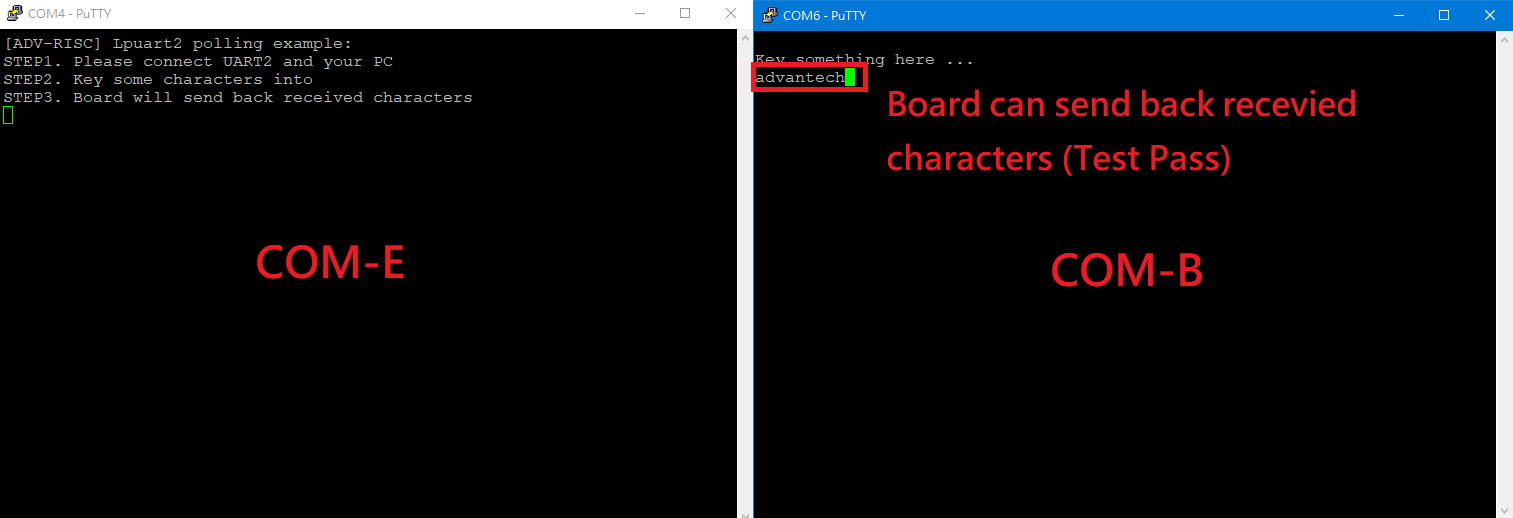
Step 5: If tester can input any characters/strings and show that at COM-B means test successful.
遠程訪問及文件傳輸(Remote Access and File Transimmion)
查看主板IP位址 ( Chech IP Address ):
Command : ifconfig<br/>
SSH访问及文件传输
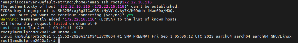
SSH Remote Log into Device
- SSH远程登录,以putty选择putty.exe(或者使用Xshell、SecureCRT等类似软件)
*需要设置远程设备的IP、通讯端口(默认22)、通讯方式,登录后验证用户名密码
通用方法(General Method)
=== 查看CPU温度(Check CPU Temperature) ===
root@imx8ulprom2620a1:~# cat /sys/devices/virtual/thermal/thermal_zone0/temp<br/> 37000
=== 查看内存容量(Check Memory Capacity) ===
root@imx8ulprom2620a1:~# free -h<br/> total used free shared buff/cache available<br/> Mem: 895Mi 230Mi 469Mi 29Mi 195Mi 546Mi<br/> Swap: 0B 0B 0B<br/> root@imx8ulprom2620a1:~#<br/>
=== 查看存储容量(Check Storage Capacity) ===
root@imx8ulprom2620a1:~# df -hT<br/> Filesystem Type Size Used Avail Use% Mounted on<br/> /dev/root ext4 15G 3.9G 9.5G 30% /<br/> devtmpfs devtmpfs 431M 4.0K 431M 1% /dev<br/> tmpfs tmpfs 448M 0 448M 0% /dev/shm<br/> tmpfs tmpfs 180M 20M 160M 11% /run<br/> tmpfs tmpfs 4.0M 0 4.0M 0% /sys/fs/cgroup<br/> tmpfs tmpfs 448M 76K 448M 1% /tmp<br/> tmpfs tmpfs 448M 1.5M 447M 1% /var/volatile<br/> tmpfs tmpfs 90M 4.0K 90M 1% /run/user/0<br/> /dev/mmcblk0p1 vfat 84M 32M 52M 38% /run/media/boot-mmcblk0p1<br/> /dev/mmcblk2p2 ext4 29G 11G 17G 40% /run/media/root-mmcblk2p2<br/> /dev/mmcblk2p1 vfat 84M 32M 52M 38% /run/media/boot-mmcblk2p1<br/> root@imx8ulprom2620a1:~#<br/>
=== 設置RTC (RTC Setting) ===
root@imx8ulprom2620a1:~# systemctl stop ntpdate.service<br/> root@imx8ulprom2620a1:~# date 090816072021 && hwclock -w && date<br/> Wed Sep 8 16:07:00 UTC 2021<br/> Wed Mar 6 04:31:37 UTC 2024<br/> root@imx8ulprom2620a1:~# date<br/> Wed Mar 6 04:31:44 UTC 2024<br/> root@imx8ulprom2620a1:~#
查看系統時間 (Check the system)
root@imx8ulprom2620a1:/# timedatectl
[ 41.402592] kauditd_printk_skb: 6 callbacks suppressed
[ 41.402611] audit: type=1334 audit(45.332:16): prog-id=15 op=LOAD
[ 41.417884] audit: type=1334 audit(45.344:17): prog-id=16 op=LOAD
Local time: Thu 1970-01-01 00:00:46 UTC
Universal time: Thu 1970-01-01 00:00:46 UTC
RTC time: Thu 1970-01-01 00:00:45 <----- Real-Time Clock,RTC
Time zone: Universal (UTC, +0000) <------ Time zone 目前
System clock synchronized: no
NTP service: active
RTC in local TZ: no
Note :
Change Time Zone
<code data-highlighted="yes">sudo timedatectl set-timezone "Asia/Taipei"<br/> </code>
           Local time: Fri 2024-05-03 09:07:42 CST
            Universal time: Fri 2024-05-03 01:07:42 UTC
                 RTC time: Fri 2024-05-03 09:07:42
                 Time zone: Asia/Taipei (CST, +0800)
 System clock synchronized: yes
               NTP service: active
               RTC in local TZ: yes
Time Zone List
$ sudo timedatectl list-timezones
Africa/Abidjan
Africa/Accra
Africa/Addis_Ababa
Africa/Algiers
Africa/Asmara
Africa/Bamako
Africa/Bangui
Africa/Banjul
Africa/Bissau
Africa/Blantyre
Africa/Brazzaville
Africa/Bujumbura
Africa/Cairo
Africa/Casablanca
Linux BSP編譯方法(Linux BSP Compile Method)
=== Yocto 4.0 ===
|


