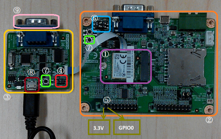
Step02: Connect the WISE-ED20 to PC using micro-USB cable.
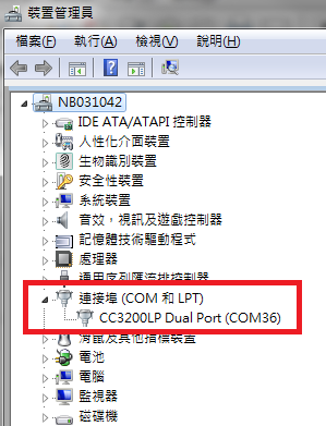
The device will be visible in the Device Manager as below after TI CC3200 SDK or FTDI driver installed. The user can refer to section "Install CC3200 SDK" for how to install CC3200 SDK.
Code Composer Studio (CCS)
The user can refer to the following steps for setup CCS with WISE-1520 SDK and get more information from section "TI".
Running CCS installer
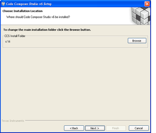
Step01: Find installer “ccs_setup_win32.exe” in source tree, run it to install CCS and set installation directory to default as below.
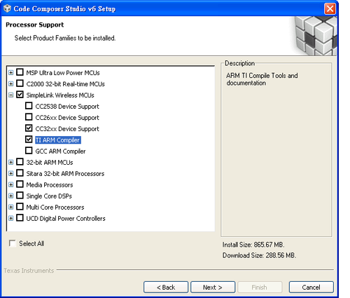
Step02: Select options as below for “Processor Support”.
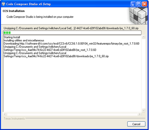
Step03: Installation process.
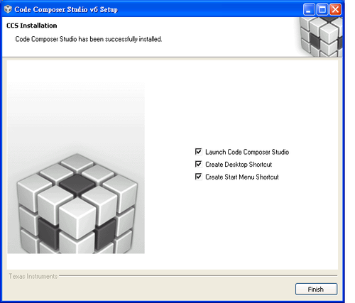
Step04: Finish installation.
Install TI-RTOS
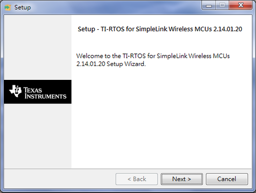
Step01: Find installer “tirtos_simplelink_setupwin32_2_14_01_20.exe” in source tree and run it to install TI-RTOS.
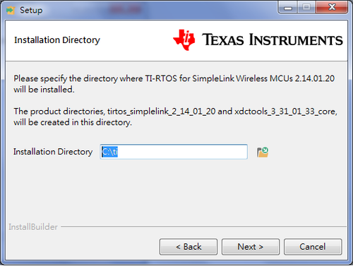
Step02: Set installation directory to default as below.
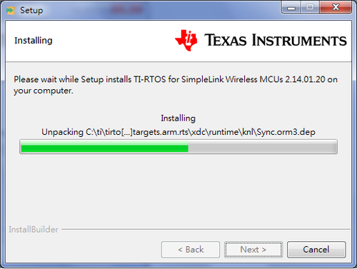
Step03: Installation process.
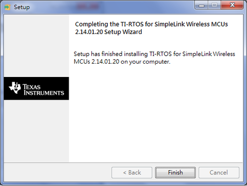
Step04: Finish installation.
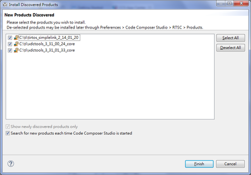
Step05: You can discover new options of TI-RTOS after installation complete when you restart CCS.
Step06: Restart CCS again to take effect for TI-RTOS.
Install CC3200 SDK
Step01: Find installer “CC3200SDK-1.1.0-windows-installer.exe” in source tree and run it to Install CC3200 SDK.
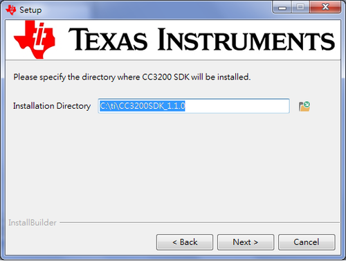
Step02: Set installation directory to default as below.
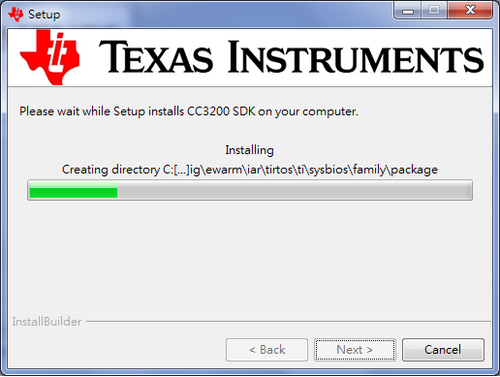
Step03: Installation process.
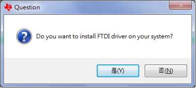
Step04: Install FTDI driver.
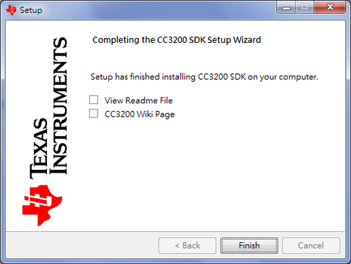
Step05: Finish installation.
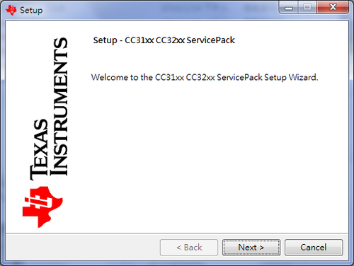
Install CC3200 Service Pack
Step01: Find installer “CC31xx_CC32xx_ServicePack-1.0.0.10.0-windows-installer” in source tree and run it to Install CC3200 service pack.
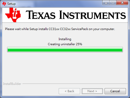
Step02: Installation process.
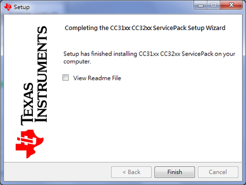
Step03: Finish installation.
Import Project
Step01: Launch CCS.
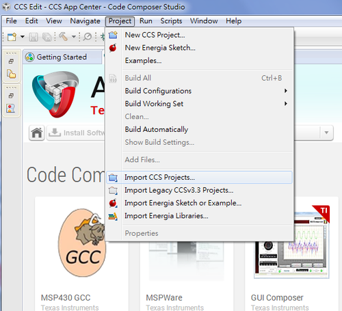
Step02: Choose Project -> Import CCS Projects from the menu.
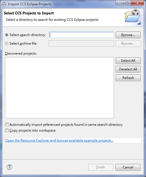
Step03: Select the Browse button in the Import CCS Eclipse Projects dialog.
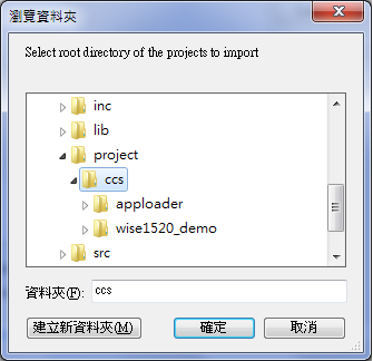
Step04: Select the CCS project directory of WISE-1520 SDK where you extracted before to root directory. For e.g. D:\WISE-1520_SDK_VX.X.X\project\ccs
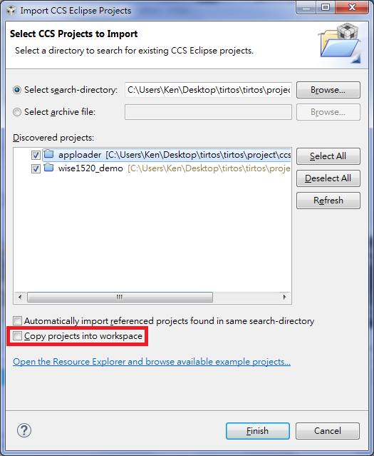
Step05: Import projects as below and press “Finish” button.
Don’t check the “Copy projects into workspace” box.
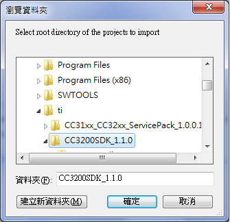
Step06: Select the Browse button in the Import CCS Eclipse Projects dialog, and Select the directory of CC3200 SDK from default path (C:\TI\CC3200SDK_1.1.0) as below.
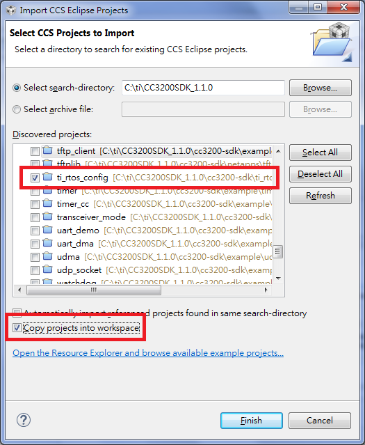
Step07: Import “ti_rtos_config” project and check the 'Copy projects into workspace' as below and press “Finish” button.
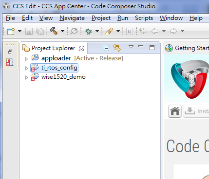
Step08: You can see imported projects as below in “Project Explorer”.
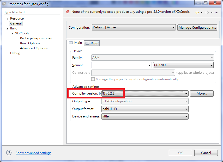
Step09: Select the ti_rtos_config project in Project Explorer, and select Project -> Properties from the menu and setup the ti_rtos_config project configuration as below.
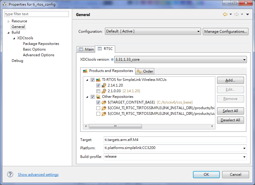
Step10: Setup the ti_rtos_config project configuration as below and press “OK” button to complete setting.
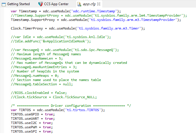
Step11: Select the ti_rtos_config project in Project Explorer and double click on “app.cfg” to open “app.cfg”.
Step12: Append driver configuration to end of “app.cfg” as below.
Note. The user can copy code as below to “app.cfg”.
/* ================ Driver configuration ================ */
var TIRTOS = xdc.useModule('ti.tirtos.TIRTOS');
TIRTOS.useGPIO = true;
TIRTOS.useUART = true;
TIRTOS.useI2C = true;
TIRTOS.usePWM = true;
TIRTOS.useSPI = true;
Compile and Debug
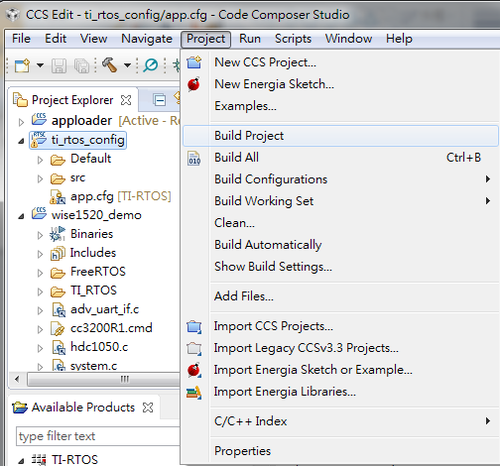
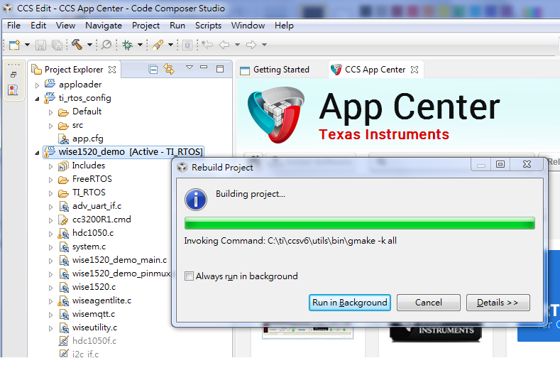
Step01: Select the ti_rtos_config project in Project Explorer, and select Project -> Build Project to build it.
Step02: Select the wise1520_demo project in Project Explorer, and select Project -> Build Project to build it.
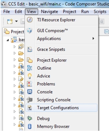
Step03: Set target configuration before debugging from CCS. Select View -> Target Configurations.
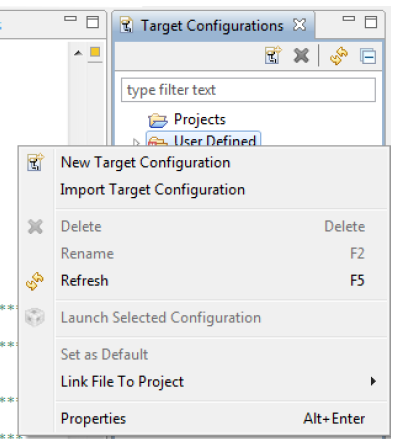
Step04: Right click on “User Defined,” select “Import Target Configuration” and select the file CC3200.ccxml from C:\TI\CC3200SDK_1.1.0\cc3200-sdk\tools\ccs_patch\. Select the Copy files option when prompted.
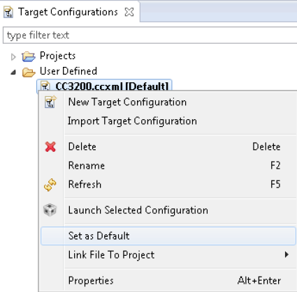
Step05: Set this new configuration as the default by right clicking on the file name as below.
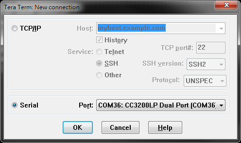
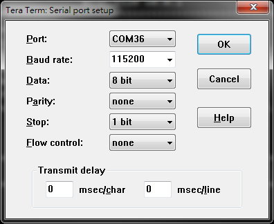
Step06: Check device connected from WISE-ED20 to PC using micro-USB cable and choose any terminal you like. (e.g., the snapshot is setting of Tera Term.)
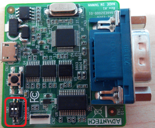
Step07: Set into programming mode.
Please check pin1 of SW2 to “ON” on WISE-ED20.
Step08: Launch application.
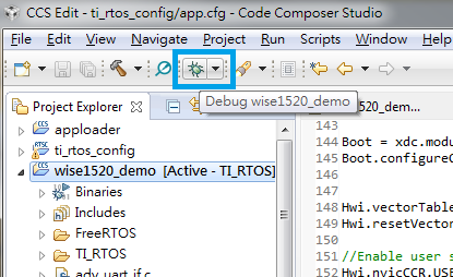
Select the wise1520_demo project in Project Explorer, and then click the debug icon as below to download code to the device and begin debugging. Press F8 to begin execution.
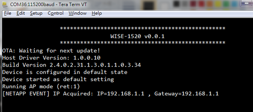
Step09: User can see snapshot as below after begin execution.
Flash Programming
Please refer to the following steps for flash programming.
Running UniFlash Installer
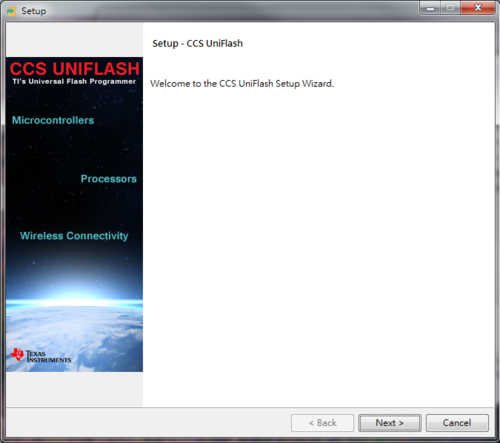
Step01: Find installer “uniflash_setup_3.4.0.00002.exe” in source tree and run it to Install UniFlash.
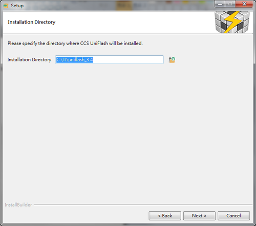
Step02: Set installation directory to default as below.
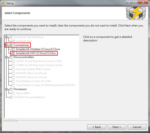
Step03: Select SimpleLink WiFi CC31xx/CC32xx to install.
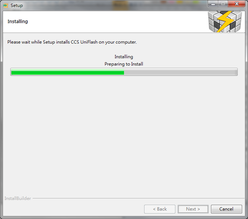
Step04: Installation process.
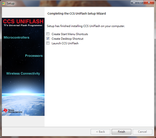
Step05: Finish installation.
Programming
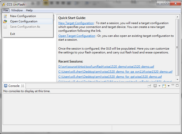
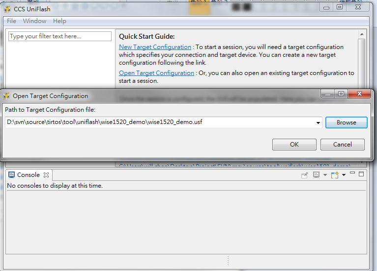
Step01: Launch UniFlash and load configuration.
Select the File -> Open Configuration, and Select the browse button to load file “WISE-XXXX_SDK_VX.X.X\tools\uniflash\wisexxxx_demo\wisexxxx_demo.usf ” from source tree of WISE-1520 SDK where you extracted before.
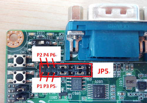
Step02: Isolate UART0 from WISE-1500.
Note: For using UART0 as debug port connected PC to CN5(DSUB) on WISE-1500, only pin5 and pin6 need to be shorted.
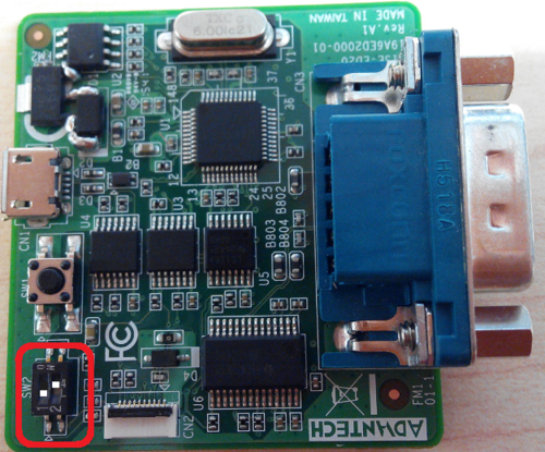
Step03: Set into programming mode.
Please check pin1 of SW2 to “ON” on WISE-ED20 for flash programming by UniFlash.
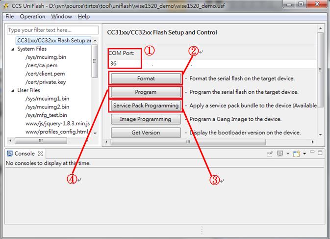
Step04: Programming by following steps.
① Check which com port you connected to device.
② Format all flash.
③ Programming for service pack. Select the file “servicepack_1.0.0.10.0.bin” from C:\TI\CC31xx_CC32xx_ServicePack_1.0.0.10.0.
④ Programming for all files.
Step05: Set into boot mode.
Please check pin1 of SW2 to “OFF” on WISE-ED20.
Step06: Boot from flash.
Press reset button and you can see snapshot as below.
Web Service
The web service will show you information and setting about WISE-1520. The user can get it in more detailed as below subsections.
Main Page
Step01: Set into AP mode.
Please check both 3.3V and GPIO0 of CN2 are shorted on WISE-1500 and press reset button to restart device into AP mode.
Step02: Connect to device.
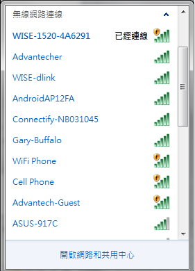
The user can connect her/his WiFi enabled device PC/Smartphone to WISE-1520 which is connected with default SSID “WISE-1520-<mac address>” and security type “OPEN”. The snapshot is showing that the notebook is connected to device.
Step03: Open main page.
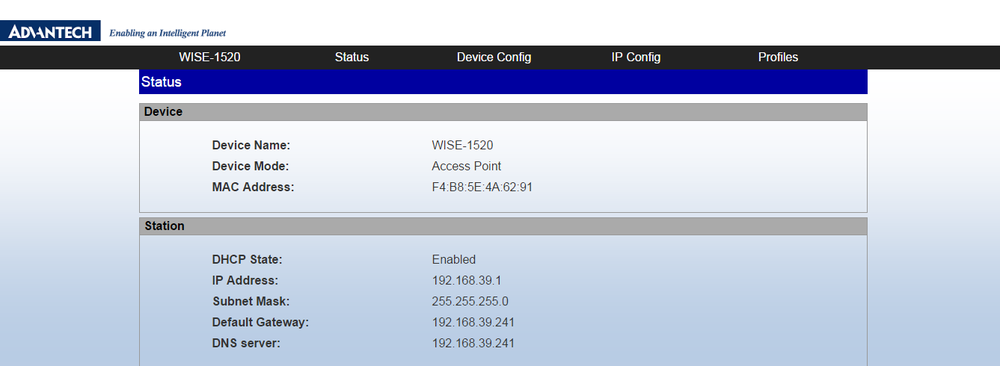
Open browser, go to http://192.168.1.1 or http://wise1520.net and login by default account/password (admin/admin).
WiFi Connectivity Setting
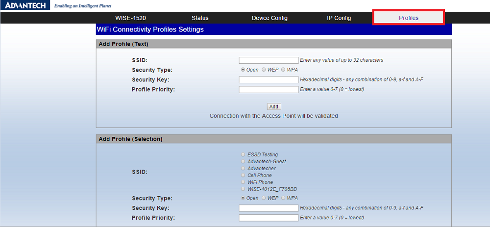
Step01: Open page “Profiles”.
Select item “Profiles” on top of main page.
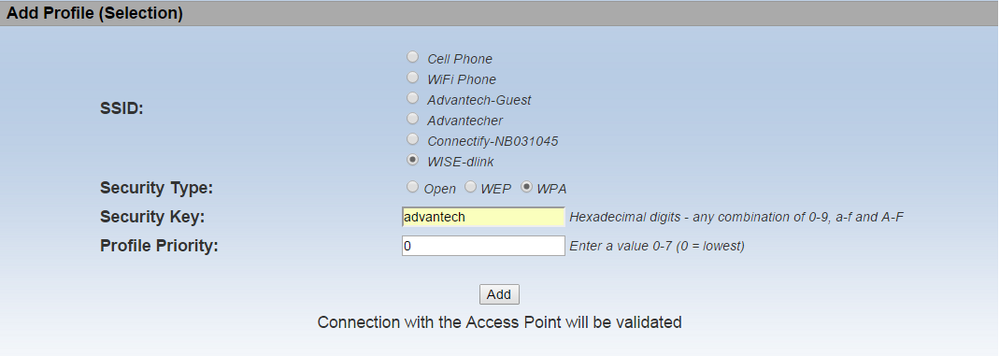
Step02: Create new session with method “Text” or “Selection”.
Fill in all columns of SSID, Security Type, Security Key and Profile Priority as below.
Create new session in “Text”.
Create new session in “Selection”
Step03: Check status.
After the connection is successful to AP and this page is refreshed, the user will see the profile you input in the "Profiles" table as below.
Note: During connection status check, user’s device PC/Smartphone might connect to different AP, user needs to reconnect to WISE-1520 device again.
AgentLite
Step01: Open page “Device Config”.
Select item “Device Config” on top of main page.
Step02: Fill in field “Server Name” of WISE AgentLite.
The user can change field "Server Name” to fill in URL or IP address that is used to connect to WISE-PaaS server or iGW in station mode after restart device.
Firmware Upgrade
This function should be enabled with OTA. Please refer to "OTA Example" firstly.
Step01: Open page “Device Config”.
Select item “Device Config” on top of main page.
Step02: Create new session with method “Text” or “Selection”.
Fill in all columns of SSID, Security Type, Security Key and Profile Priority as below.
Run firmware upgrade.
① The user must to fill field "Key” in token obtained from Dropbox that is used to be authenticated with Dropbox server.
② Press “Upgrade” button to run firmware upgrade.
Step03: Check status.
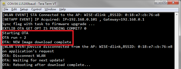
① Check status from terminal as below.
② Please refer to section "Firmware Version" for checking firmware version.
Figure1: Starting OTA to download new firmware and reboot device.
Figure2: Perform commit flag to finish firmware upgrade after device booting.
Remote Reset
Step01: Open page “Device Config”.
Select item “Device Config” on top of main page.
Step02: Press “Reset” button to reset device.
Account/Password
Step01: Open page “Device Config”.
Select item “Device Config” on top of main page.
Step02: Change username and password.
Fill in all columns of Username, Password and Confirm Password as below, and then press “Apply” button.
RTC
Step01: Open page “Status”.
Select item “Status” on top of main page.
Step02: Set RTC.
Press “Set Time to Current” button to set RTC.
Firmware Version
Step01: Open page “Status”.
Select item “Status” on top of main page.
Step02: By default you should see both Advantech version and TI version.
Example
WISE-1520 Demo
There are two mainly examples including AgentLite and OTA the user can refer to it for how to implement it from file “wise1520_demo_main.c” in folder “src/example” of source tree of WISE-1520 SDK. By the way, the user can enable or disable these examples by macro “AGENT_APP_EXAMPLE “and “OTA_APP_EXAMPLE” to decide whether compiled these function into binary or not. In addition to last two examples, the source code of web configuration is also in file “wise1520_demo_main.c” as default.
The default enabled function on WISE-1520 module from manufacture only includes AgentLite and web service and the default debug port is set by UART1. On the other hand, the UART0 is used to print out debug message as default in our examples. The user can use UART1 as debug port by macro “USE_UART1” in compilation.
The WISE-1520 Demo has been implemented based on TI CC3200 SDK and TI RTOS. If the user wants to know in more detailed what the example does, the user must to study domain knowledge about TI CC3200 SDK and TI RTOS that should be found from section "TI".
Detailed about WISE-1520 Demo
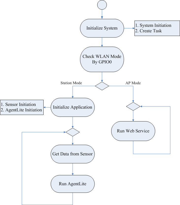
The detailed behavior about this example is explained as following:
- Initiation hardware, multi-function pin, task…etc.
- Booting device with station mode or AP mode is decided by checking GPIO0.
- The GPIO0 is checked as default to decide which mode is enabled when booting device. After application running into infinite loop, the user can take GPIO0 back controlled by self.
- Initiation sensor and access data from it.
- The TI HDC1050 has been design-in on WISE-1500. It’s a digital humidity sensor with integrated temperature sensor. The HDC1050 is initialized in example and the user can get data of humidity and temperature from it. The driver of HDC1050 named as “hdc1050.c” is located in folder “src/sensor/ti” of source tree of WISE-1520 SDK and the user should refer to it for how to implement driver on WISE-1520 module. Due to the “hdc1050.c” is implemented based on TI RTOS driver framework, the user must to study know how about TI RTOS driver framework and can read it at section “TI-RTOS Drivers” in document “tirtos_User_Guide.pdf” that can be obtained from section "TI".
- Loop in AgentLite or web service.
- When device booting into station mode, it is going to infinite loop for AgentLite. There are many things needed to do including connected to WISE-PaaS server, keep getting data from sensor and data exchanged through AgentLite. On the other hand, when device booting into AP mode, it is going to infinite loop for web service.
The flowchart is about example how to running as below figure.
Flowchart of WISE-1520 demo
Import WISE-1520 Demo
Please refer to section "Import Project" for how to import project of WISE-1520 Demo.
AgentLite Example
Setup for WISE-PaaS
- Please refer to link "WISEAgentLite" to understand how to using AgentLite API and how to setup for WISE-PaaS.
Setup for Device
- Step01: Enable macro “AGENT_APP_EXAMPLE” and “USE_SENSOR” in CCS.
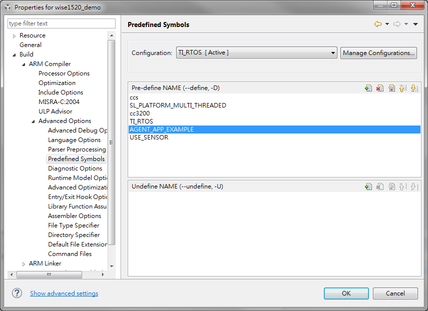
- Select the wise1520_demo project in Project Explorer, and select Project -> Properties to check “AGENT_APP_EXAMPLE” that should be added into Build -> ARM Compiler -> Advanced Options -> Predefined Symbols as below.
- Step02: Compile example
- Select the wise1520_demo project in Project Explorer, and select Project -> Build Project to build it.
- Step03: Programming
- Please refer to section "Flash Programming" for how to do flash programming.
- Step04: Set into AP mode and press reset button to restart device.
- Please check both 3.3V and GPIO0 of CN2 are shorted on WISE-1500 as below.
-
- Note: Refer to section "Preparing for Hardware" for more information about hardware if user needed.
- Step05: Create WiFi Connectivity Profile.
- Please refer to section "WiFi Connectivity Setting" for how to do it.
- Step06: Set into station mode and press reset button to restart device.
- Please check both 3.3V and GPIO0 of CN2 are opened on WISE-1500 as below.
-
- Note: Refer to section "Preparing for Hardware" for more information about hardware if user needed.
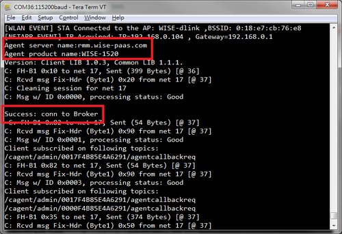
- Step07: Check connection successful to WISE-PaaS from terminal.
- The device is connected to server by “rmm.wise-paas.com” and connection to broker successful as below. The “rmm.wise-paas.com” can be modified by user and please refer to section "AgentLite" for how to do it.
-
OTA Example
The “Over the Air” (OTA) is method for software update. The new application hosted in cloud can be updated into WISE-1520. For doing this example, the user needs to setup between WISE-1520 and cloud service, and require project of Application Loader running together. The user can refer to section "Application Loader" for how to setup for Application Loader and section "TI" for more information about OTA.
There is size limitation about OTA example with WISE-1520 SDK. The user must to check the total size of both MCU images, one is programmed to internal SPI flash and another is hosted in cloud service, are less than approximately 214 Kbytes.
Setup for Cloud Service
- Currently it is only supported Dropbox as default cloud service. Please first create account with Dropbox if you never do before.
- Create an account with Dropbox and login.
- Go to https://www.dropbox.com/developers/apps/create , then select “Dropbox API” and “App folder – Access to a single folder created specifically for your app”.
- Provide a suitable name for the APP and click “Create APP” button.
- The page will be redirected to Apps setting page. Scroll down to “Generated access token” and click generate. Copy and save the generated token.
- Go to https://www.dropbox.com/home/Apps.
- Click on the application name.
- Create a new folder and name it “WISE-1520 vX.X.X” that you should check it whether the same as macro “DEMO_VERSION” from source code of example in SDK.
- This folder will contain new firmware that is named as “f80_sys_mcuimgA.bin” and uploaded by user.
- Note: The user should find the method for how to produce new firmware as below subsection "Setup for WISE-1520".
Setup for WISE-1520
- Step01: Enabled macro “OTA_APP_EXAMPLE” in CCS.
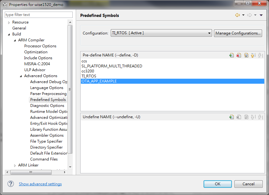
- Select the wise1520_demo project in Project Explorer, and select Project -> Properties to check “OTA_APP_EXAMPLE” that should be added into Build -> ARM Compiler -> Advanced Options -> Predefined Symbols as below.
- Note: Only “OTA_APP_EXAMPLE” should be enabled due to size limitation of internal SPI flash on WISE-1520 module.
- Step02: Produce new firmware and upload it to cloud.
- ① Modify string of macro “DEMO_VERSION” to “WISE-1520 vX.X.X+1” that it’s mean next version of new firmware you want to show in web service.
- ② Select the wise1520_demo project in Project Explorer, and select Project -> Build Project to build it.
- ③ Rename filename “wise1520_demo.bin “ from folder “WISE-1520_SDK_VX.X.X\project\ccs\wise1520_demo\TI_RTOS” to “f80_sys_mcuimgA.bin” and upload it to cloud.
- Note: The user can refer to section "Setup for Cloud Service" as above for how you could upload new firmware to cloud.
- Step03: Modify and save web page for OTA.
- Remove HTML comment tag <!-- and --> from WISE-1520_SDK_VX.X.X\tool\uniflash\wise1520_demo\dev_config.html for form of firmware upgrade as below:
- <form method=POST name="WISE-1520 Configuration" action="nothing" onsubmit="return fHandleKey()" >
<tr><td class=empty-line colspan=2></td></tr><tr><td class=frame-title colspan=2>"Firmware Upgrade"</td>
…………………………………………………………………………………………………………………….
- </form>
- Step04: Programming firmware of current version.
- Restore string of macro “DEMO_VERSION” to “WISE-1520 vX.X.X” and rebuild it.
- This “wise1520_demo.bin “ will be programmed to device by UniFlash.
- Note: Refer to section "Flash Programming" for how to do flash programming.
- Step05: Set into AP mode and press reset button to restart device.
- Please check both 3.3V and GPIO0 of CN2 are shorted on WISE-1500 as below.
-
- Note: Refer to section "Preparing for Hardware" for more information about hardware if user needed.
- Step06: Run firmware upgrade on web service.
- Please refer to section "Firmware Upgrade" for how to do it.
ADC Example
HW description
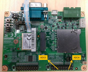
The WISE-1520 has two ADC (analog to digital converter) channels, ADC0 and ADC4. The ADC0 is at M2.COM pin50 and WISE-DB1500 CN3.pin7.
The ADC4 is at M2.COM pin59 and WISE-DB1500 CN3.pin15.
FW implement
Add below code in wise_1520_main.c or download wise1520_demo_main.zip and unzip.
Step 1: add header file
//Common interface file in CC3200 SDK
#include "common.h"
#include "gpio_if.h"
#include "adc.h"
#include "adc.h" // add header file.
Step 2: add function declare
//*******************************************************************
// Local functions prototypes
//*******************************************************************
…
static float ADC_ReadDatByChannel(uint32_t Channel);
…
define NO_OF_SAMPLES 128 // define sample times
Step 3: add code in caller
void ConnectionTask(void* pTaskParams){
…
…
float fADC0_v;
float fADC4_v;
…
fADC0_v=ADC_ReadDatByChannel(0);
UART_PRINT("[ADC0]: %f \n\r", fADC0_v);
fADC4_v=ADC_ReadDatByChannel(4);
UART_PRINT("[ADC4]: %f \n\r", fADC4_v);
}
Step 4: function implement
float ADC_ReadDatByChannel(uint32_t Channel){
uint32_t uiChannel;
uint32_t uiIndex=0;
uint32_t ulSample;
float fSample = 0.0;
switch(Channel)
{
case 0:
uiChannel = ADC_CH_3;
MAP_PinTypeADC(PIN_60, PIN_MODE_255);
break;
case 4:
uiChannel = ADC_CH_1;
MAP_PinTypeADC(PIN_58, PIN_MODE_255);
break;
default:
return -1.0;
}
MAP_ADCTimerConfig(ADC_BASE,2^17);
MAP_ADCTimerEnable(ADC_BASE);
MAP_ADCEnable(ADC_BASE);
MAP_ADCChannelEnable(ADC_BASE, uiChannel);
while(uiIndex < NO_OF_SAMPLES + 4)
{
if(MAP_ADCFIFOLvlGet(ADC_BASE, uiChannel))
{
ulSample = MAP_ADCFIFORead(ADC_BASE, uiChannel);
//to voltage
fSample = ((float)((ulSample>>2) & 0x0FFF)*1.48 )/4096.0;
uiIndex++;
}
}
MAP_ADCChannelDisable(ADC_BASE, uiChannel);
switch(Channel)
{
case 0:
MAP_PinTypeGPIO(PIN_60, PIN_MODE_0, false);
MAP_GPIODirModeSet(GPIOA0_BASE, 0x20, GPIO_DIR_MODE_IN);
break;
case 4:
MAP_PinTypeGPIO(PIN_58, PIN_MODE_0, false);
MAP_GPIODirModeSet(GPIOA0_BASE, 0x8, GPIO_DIR_MODE_IN);
break;
}
return fSample;
}
ADC Result
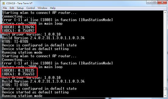
See the ADC value in debug message below picture.
Application Loader
The application loader is loaded by 1st stage loader in the ROM. The user can get it for loading multi-images or other purposes. This example is used to demonstrate how to loading two applications in flash, one is loaded as default and the other is loaded when any keys is pressed on terminal.
Import Application Loader
Please refer to section "Import Project" for how to import project of Application Loader.
Application Loader Example
Step01: Compile example.
Select the “apploader” project in Project Explorer, and select Project -> Build Project to build it.
Step02: Launch UniFlash and load configuration.
Please refer to section "Programming" for how to do it.
Step03: Compile and create two binaries.
Please refer to subsection "Setup for WISE-1520" until step 3 for how to creating two binaries, one is “wise1520_demo.bin “build-in version “WISE-1520 vX.X.X” and the other is “f80_sys_mcuimgA.bin” build-in version “WISE-1520 vX.X.X+1”.
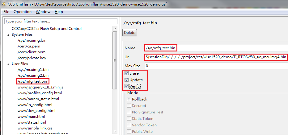
Step04: Check options for programming “f80_sys_mcuimgA.bin” binary as below.
① Select “/sys/mfg_test.bin”.
② Fill in filed “Url” to specify file path where the “f80_sys_mcuimgA.bin” it is.
③ Check the Erase, Update, Verify boxes.
Step05: Programming into flash and booting from it.
Refer to section "Flash Programming" for how to do flash programming.
Step06: Run the program the user specifies.
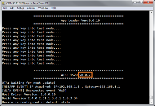
① The figure 1 is running “wise1520_demo.bin “build-in version “WISE-1520 vX.X.X”.
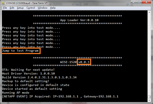
② The figure 2 is running “f80_sys_mcuimgA.bin” build-in version “WISE-1520 vX.X.X+1” when the user press any key on terminal.
Figure1: The “wise1520_demo.bin “ is booted as default.
Figure2: The “f80_sys_mcuimgA.bin” is booted when the user press any key on terminal.
Appendix
References
TI
About example located at default path(C:\TI\CC3200SDK_X.X.X\cc3200-sdk\docs\examples):
- CC3200 Over-The-Air (OTA) Update Application Note.pdf
About TI CC3200 SDK located at default path(C:\TI\CC3200SDK_X.X.X\cc3200-sdk\docs):
About TI RTOS located at default path (C:\TI\tirtos_simplelink_X_XX_XX_XX\docs):
- tirtos_cc32xx_Getting_Started_Guide.pdf
- tirtos_User_Guide.pdf
About development tools:
The more about CC3200:
Memory/Flash Usage
The WISE-1520 has 1 MBytes flash and 256 KBytes RAM.
Flash with MP default Setup (1 block is 4KB):
| Used Space
|
Free Space
|
| 203 Blocks
|
53 Blocks
|
- Enabled functions with MP default Setup
| File Index
|
Start Block
|
Size [Blocks]
|
Fail Safe
|
Total Size [Blocks]
|
Filename
|
| N/A
|
0
|
5
|
N/A
|
5
|
FATFS
|
| 0
|
81
|
4
|
yes
|
8
|
/sys/mcuimg.bin
|
| 4
|
5
|
5
|
yes
|
10
|
/tmp/phy.cal
|
| 6
|
15
|
33
|
yes
|
66
|
/sys/servicepack.ucf
|
| 7
|
89
|
31
|
no
|
31
|
/sys/mcuimg2.bin
|
| 8
|
120
|
28
|
no
|
28
|
/sys/mfg_test.bin
|
| 9
|
148
|
3D
|
no
|
3
|
www/profiles_config.html
|
| 10
|
151
|
1
|
no
|
1
|
www/param_status.html
|
| 11
|
152
|
2
|
no
|
2
|
www/ip_config.html
|
| 12
|
154
|
5
|
no
|
5
|
www/dev_config.html
|
| 13
|
159
|
1
|
no
|
1
|
www/main.html
|
| 14
|
160
|
2
|
no
|
2
|
www/status.html
|
| 15
|
162
|
3
|
no
|
3
|
www/simple_link.css
|
| 16
|
165
|
1
|
no
|
1
|
www/imgaes/advantech.png
|
| 17
|
166
|
1
|
no
|
1
|
/etc/product_info.txt
|
| 18
|
167
|
1
|
no
|
1
|
/etc/burning_onoff.txt
|
| 19
|
168
|
1
|
no
|
1
|
/cert/ca.der
|
| 20
|
169
|
1
|
no
|
1
|
/cert/client.der
|
| 21
|
170
|
1
|
no
|
1
|
/cert/ckey.der
|
| 22
|
171
|
2
|
no
|
2
|
www/agentlite.html
|
| 23
|
173
|
4
|
no
|
4
|
www/imgaes/hw_07_short_web.png
|
| 24
|
177
|
1
|
yes
|
2
|
/sys/mcubootinfo.bin
|
| 26
|
179
|
1
|
yes
|
2
|
/sys/stacfg.ini
|
| 27
|
181
|
1
|
yes
|
2
|
/sys/appcfg.bin
|
| 28
|
183
|
1
|
yes
|
2
|
/sys/devname.cfg
|
| 29
|
185
|
1
|
yes
|
2
|
/sys/ap.cfg
|
| 30
|
187
|
1
|
yes
|
2
|
/sys/ipcfg.ini
|
| 31
|
189
|
1
|
yes
|
2
|
/sys/dhcpsrv.cfg
|
| 32
|
191
|
1
|
yes
|
2
|
/sys/httpsrv.cfg
|
| 33
|
193
|
2
|
yes
|
4
|
/sys/pref.net
|
| 34
|
197
|
1
|
yes
|
2
|
/sys/mode.cfg
|
| 35
|
199
|
1
|
yes
|
2
|
/sys/pmcfg.ini
|
| 36
|
201
|
1
|
yes
|
2
|
/sys/mdns.cfg
|
Flash with OTA Setup (1 block is 4KB):
| Used Space
|
Free Space
|
| 238 Blocks
|
18 Blocks
|
- Enabled functions with OTA Setup
| File Index
|
Start Block
|
Size [Blocks]
|
Fail Safe
|
Total Size [Blocks]
|
Filename
|
| N/A
|
0
|
5
|
N/A
|
5
|
FATFS
|
| 0
|
81
|
4
|
yes
|
8
|
/sys/mcuimg.bin
|
| 4
|
5
|
5
|
yes
|
10
|
/tmp/phy.cal
|
| 6
|
15
|
33
|
yes
|
66
|
/sys/servicepack.ucf
|
| 7
|
89
|
31
|
no
|
31
|
/sys/mcuimg2.bin
|
| 8
|
120
|
3
|
no
|
3
|
www/profiles_config.html
|
| 9
|
123
|
1
|
no
|
1
|
www/param_status.html
|
| 10
|
124
|
2
|
no
|
2
|
www/ip_config.html
|
| 11
|
126
|
5
|
no
|
5
|
www/dev_config.html
|
| 12
|
131
|
1
|
no
|
1
|
www/main.html
|
| 13
|
132
|
2
|
no
|
2
|
www/status.html
|
| 14
|
134
|
3
|
no
|
3
|
www/simple_link.css
|
| 15
|
137
|
1
|
no
|
1
|
www/imgaes/advantech.png
|
| 16
|
138
|
1
|
no
|
1
|
/cert/ca.der
|
| 17
|
139
|
1
|
no
|
1
|
/cert/client.der
|
| 18
|
140
|
1
|
no
|
1
|
/cert/ckey.der
|
| 19
|
141
|
2
|
no
|
2
|
www/agentlite.html
|
| 20
|
143
|
4
|
no
|
4
|
www/imgaes/hw_07_short_web.png
|
| 21
|
147
|
1
|
yes
|
2
|
/sys/mcubootinfo.bin
|
| 22
|
149
|
1
|
yes
|
2
|
/sys/stacfg.ini
|
| 23
|
151
|
1
|
yes
|
2
|
/sys/appcfg.bin
|
| 24
|
153
|
1
|
yes
|
2
|
/sys/devname.cfg
|
| 26
|
155
|
1
|
yes
|
2
|
/sys/ap.cfg
|
| 27
|
157
|
1
|
yes
|
2
|
/sys/ipcfg.ini
|
| 28
|
159
|
1
|
yes
|
2
|
/sys/dhcpsrv.cfg
|
| 29
|
161
|
1
|
yes
|
2
|
/sys/httpsrv.cfg
|
| 30
|
163
|
2
|
yes
|
4
|
/sys/pref.net
|
| 31
|
167
|
1
|
yes
|
2
|
/sys/mode.cfg
|
| 32
|
169
|
1
|
yes
|
2
|
/sys/pmcfg.ini
|
| 33
|
171
|
1
|
yes
|
2
|
/sys/mdns.cfg
|
| 34
|
173
|
1
|
yes
|
2
|
/tmp/table.arp
|
| 35
|
175
|
31
|
yes
|
62
|
/sys/mcuimg3.bin
|
| 36
|
237
|
1
|
no
|
1
|
/sys/otastat.txt
|
RAM:
| SRAM_CODE
|
SRAM_DATA
|
Free Space
|
| 126 KBytes
|
87 KBytes
|
33 KBytes
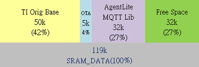
|
|
