EPD-130 application tech
Contents
EPD-130 Application guide
This application provide user a way that image full/partial update for EPD-130 panel. user should follow the different command parameter to load or display image or using .bat script combined with load and display command. Application only support on Windows platform(Windows 7、Windows 10)。
Components LIST
|
Item |
Description |
|---|---|
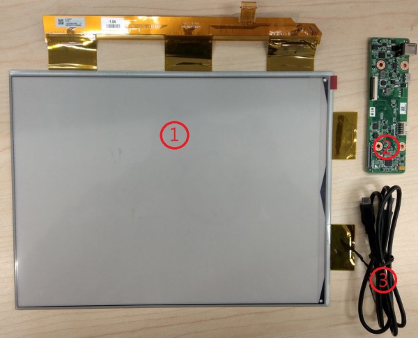
| 1 | 13.3” EPAPER |
| 2 | EPD-130 PCBA |
| 3 | cable |
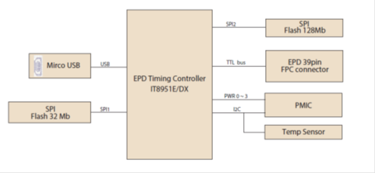
SYSTEM ARCHITECURE
Panel model
- EPD-130R : The panel has black and white color.
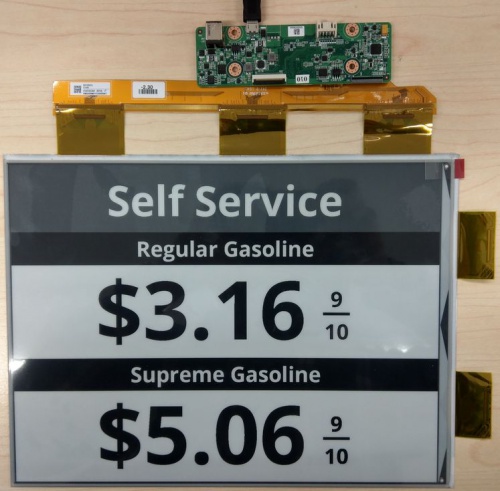
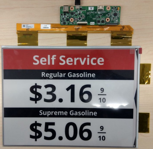
- EPD-130B : The panel has black、white and red color.
Waveform mode
There are six Waveform mode for image update and short name as below table. Waveform mode suit to EPD-130B panel model and mode parameter will use in display command.
EPD-130B waveform mode table
| mode 0 | mode 1 | mode 2 | mode 3 | mode 4 | mode 5 |
| INIT | DU | GC16 | GL16 | A2 | DU4 |
INIT(Global update WF) :
- Initialize is used to completely clear the display, if it's left in an unknown state (i.e. if the previous image has been lost by a re-boot)
DU(Local update WF) :
- Direct update Non-flashing waveform that can be used to update. it can update any changed graytone pixel to black or white only.
GC16(Global update WF) :
- Grayscale clear, 16 levels A "flashy" waveform used for 16 level grayscale images. All the pixels are updated or cleared
GL16(Local update WF when white to white , Global update when 16 gray levels) :
- The GL16 waveform is used to update anti-aliased text with reduced flash. GL16 should be used only with Full Display Update.
- The entire display except pixels staying in white will update as the new image is written. The GL16 waveform has 16 unique gray levels.
A2(Local update WF) :
- animation, 2 Levels is a non-flashing waveform that can be used for fast updates and simple animation.
- This wave form support black & white updates only.
- image quality and ghosting is reduced in exchange for the response time.
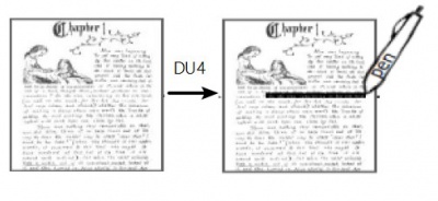
DU4(Local update WF) :
- A fast update time(simlar to DU), non-flashy waveform.
- This mode supports transitions from any graytone to graytone 0(Black),5,10.15(White).
- The combination of fast update time and four graytone make it useful for anti-aliased text in menus
EPD-130R waveform mode
It's only supported 0 、1、2 mode.
Mode 0 :All the pixels are cleared then All the pixels are updated in black and white elements
Mode 1 :Showing red element in picture.
Mode 2 :Do not clean all the pixels and showing black and white element in picture.
Push image application
Hardware and software prepare
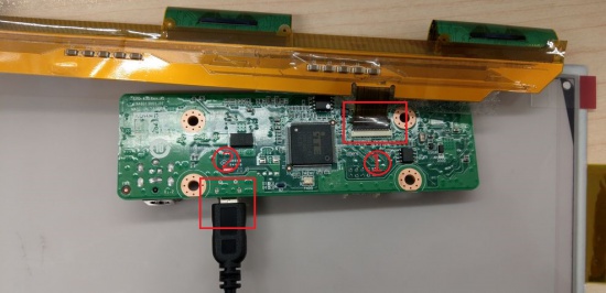
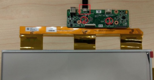
Follow steps and picture below to setup the hardware
1. Turn to back of mainboard and Connected EPD FPC to mainboard
2. Connected micro USB cable to mainboard USB2(CN5) the other side connect to desktop/laptop usb port
3. Download and unzip EPD-130_CLIv4_tool
4. Open windows command line
5. Change current directory to user's Adv_CLI_v4 tool directory on command line window
6. User can find IT8951_USB_Cmd.exe application in Adv_CLI_v4
Command tool
Using IT8951 cmd.exe tool with command parameter in detail as below
Load image
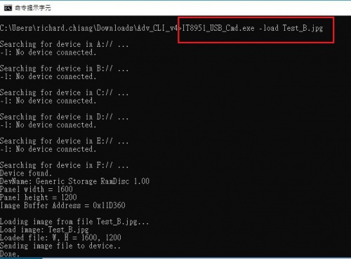
Loading selected image file to IT8951 buffer. Only supports bmp and jpg type.
Command format: IT8951_USB_Cmd.exe -load [file name]
Display
Refresh the assigned range of EPD (according to the image buffer and chosen mode)
IT8951_USB_Cmd.exe -display -wait [x] [y] [width] [height] [mode]
-wait : -wait command use on condition that IT8951 will waiting for display done to accept next command. it's avoid IT8951 image buffer to lost. -nowait: IT8951 won't waiting for display done to accept next command, User should avoid the overlap between displayed area, or it'll cause problem.
we recommend using -wait in command that make sure the display area in the right way.
x, y is the start coordinates and width, height is update range but it can not exceed the resolution. mode see Section 1.3 waveform mode
Full update
Below it explain two type example for full update image
In EPD-130B panel model. The usually full update command as below.
x、y are start coordinates (0, 0) , width 、height are (1600 , 1200).
IT8951_USB_Cmd.exe -load money.jpg
IT8951_USB_Cmd.exe -display -wait 0 0 1600 1200 2
In mode 0 ,it is used to completely clear the display when initial panel then using white image to display panel instead of mode 0. It prevents panel from damaging.
In mode 3 must use in Full update
IT8951_USB_Cmd.exe -load money.jpg
IT8951_USB_Cmd.exe -display -wait 0 0 1600 1200 3
In EPD-130R panel model. The usually full update command should use mode 0,1,2 display image.
Here mode 0 must be using updated in black and white elements and Mode 1 that is showing red element in picture. Mode 2 compensate black element
IT8951_USB_Cmd.exe -load money.jpg
IT8951_USB_Cmd.exe -display -wait 0 0 1600 1200 0
IT8951_USB_Cmd.exe -display -wait 0 0 1600 1200 1
IT8951_USB_Cmd.exe -display -wait 0 0 1600 1200 2
Partial update
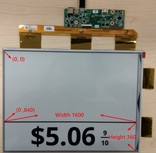
User can change start coordinate and define width, height to achieve partial display.
In EPD-130B panel model.
x, y are start coordinate and the width、height depends on user's defined.
Below command is defined start coordinate in (0, 840) and width、height is defined (1600 , 360).
IT8951_USB_Cmd.exe -load money.jpg
IT8951_USB_Cmd.exe -display -wait 0 840 1600 360 2
In mode 4 it is used for fast switching or simple animation only the conversion between black and white, sacrificing the image quality and afterimage effect for fast response time.
mode 4 (A2)scenario
In mode 5 a fast update time(simlar to DU), non-flashy waveform but it easily appear Ghosting on panel. it is suitable highlight text
In EPD-130R panel model
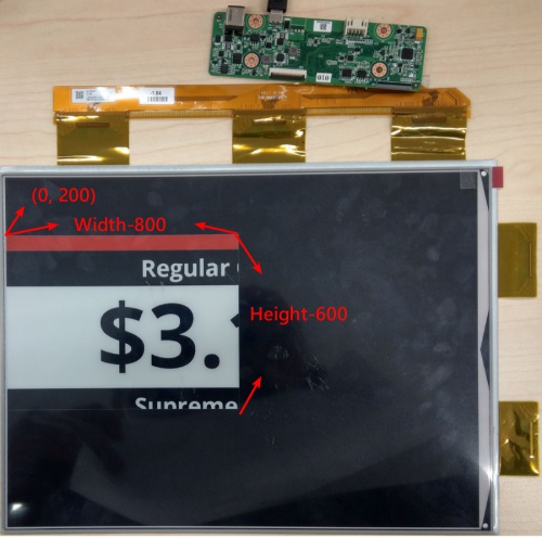
Below command is defined start coordinate in (0, 200) and width、height is defined (800 , 600). user should follow the command sequence to display.
IT8951_USB_Cmd.exe -load money.jpg
IT8951_USB_Cmd.exe -display -wait 0 200 800 600 0
IT8951_USB_Cmd.exe -display -wait 0 200 800 600 1
IT8951_USB_Cmd.exe -display -wait 0 200 800 600 2
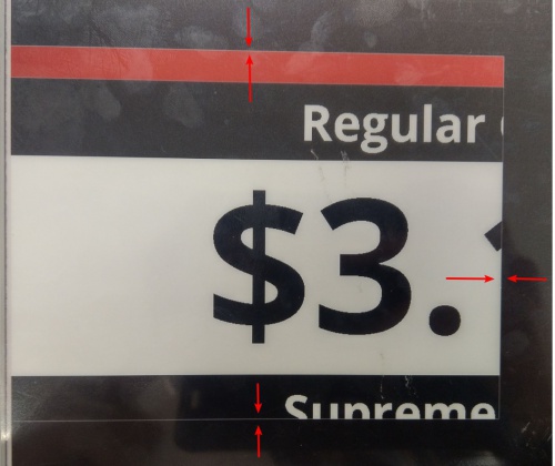
Caution after using partial update in EPD-130R panel,it will appear 1 pixel border on deep color background .
Note Panel resolution is 1600 x 1200
Panel information confirm
Using the wrong waveform & bin file may affect the display quality of the panel, all the panel and driving board has been confirmed that the waveform & bin received is consistent with the panel. Below is the label on the panel you can see
VCOM Voltage
VCOM is DC level for driving voltage, to match the panel for optimum display performance, it’s need adjustable because of each EPD display with differ VCOM value. Vcom value is necessary to match the panel label, wrong Vcom might cause permanent damage on EPD. All VCOM has been adjust into driving board before shipping to customer.
