WISE-ED22 User Manual
Contents
ED22 Functions
There are three interfaces that ED22 board provides. These are drag-n-drop programming, a serial port and debugging support. In addition ED22 board firmware can be updated using the drag-n-drop programming interface of the bootloader.
H/W Setup
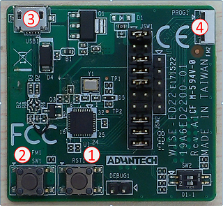
ED22 Introduction
1. ED22 board reset button.
2. Target MCU(STM32L443/STM32F412/STM32F486) reset button.
3. Micro USB connector.
4.10pin FFC connector.
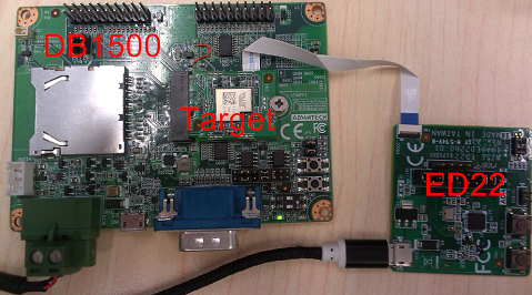
Connection with target board
Install Driver
ED22 Firmware Update
When you get a new WISE-ED22, you must perform the following steps to updated it's FW. Make WISE-ED22 suitable for your product.
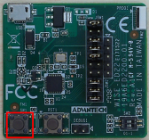
Step1: plugging ED22 in PC with the "Target MCU reset" button held down.
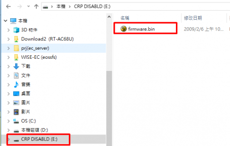
Step2: Open the "CRP Disabled" drive, and delete the file called "firmware.bin"
Step3:Copy the .bin file that corresponding to target MCU onto the "CRP Disabled" drive.
Strp4: Press ED22 board reset to restart, then you can see a disk drive called DAPLink.
WISE-ED22 FW files:
1. STM32L443: WISE-1510/WISE-1511/WISE-1540
2. STM32F412: WISE-1530/EPD-132
3. STM32L486: WISE-1570
Using ED22
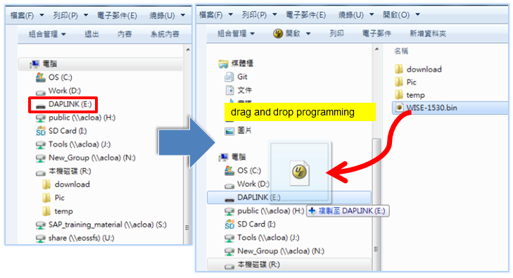
Drag-n-drop Programming
To use the ED22, simply connect to your PC with a micro-USB cable, and to the WISE-15XX board using a 10 pin FFC cable. You can drag and drop binary images onto the DAPLink disk drive, which will then be programmed into the target system.If errors are encountered, a file called "fail.txt" will appear with details.
Note that the ED22 has to contain the correct firmware to enable drag and drop programming.
Supported file formats:
- Raw binary file
- Intel Hex
Serial Port
The serial port is connected directly to the target MCU allowing for bidirectional communication. It also allows the target to be reset by
sending a break command over the serial port.
Supported baud rates:
- 9600
- 115200
Debugging
Debugging can be done with any IDE that supports the CMSIS-DAP protocol. Some tools capable of debugging are:
